
CNC Deburring Guide: 6 Methods, Tools, and Process for Burr-Free Metal Parts
Burrs ruin CNC parts, so this CNC deburring guide shows what to do.
If you ship parts with sharp edges, hidden hole-exit burrs, or smeared threads, you risk jams during assembly, leaks on sealing faces, and cosmetic rejects after anodizing or plating. Even worse, inconsistent deburring creates quote swings and quality disputes because teams never agree on what “burr-free” means.
In this guide, I break down burr types, root causes, and six proven deburring methods. You will learn how to choose the right process for your material, geometry, and volume, and how to specify edge requirements so suppliers deliver consistent results. If you want a deburring-aware quote and a fast DFM review, request a deburring-aware CNC quote.
CNC Deburring Definition
Deburring in CNC machining means you remove unwanted burrs and create a controlled edge condition. A burr is a raised edge or small piece of material left after machining, and deburring is the step that prevents that leftover material from causing fit, safety, leak, or finish issues on CNC machining parts.
What is deburring in machining
You deburr to make parts safe to handle, easier to assemble, and more consistent for inspection and finishing.
In practice, I treat deburring as a quality step, not a cosmetic cleanup. When you control edges early, you reduce downstream defects such as scratched cosmetic faces, damaged seals, and burr-driven assembly force spikes. Your inspection team also gets a clearer acceptance standard when you define the expected edge condition.
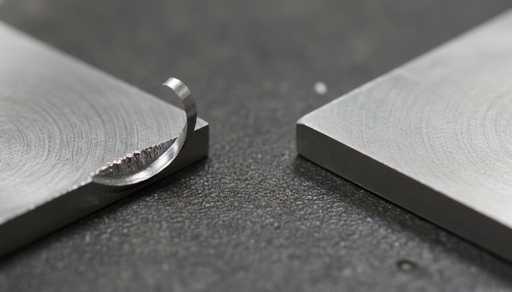
Deburr meaning and burr-free requirements for production parts
“Deburr” usually means you remove burrs and break sharp edges, but “burr-free” needs tighter language in production. If your drawing only says “deburr all edges,” suppliers must guess how much edge break you allow, which creates quote swings and inconsistent results. A production-ready burr-free requirement specifies where burrs are unacceptable and what edge condition you want.
ISO 13715 helps teams communicate undefined edge conditions using a standardized indication and dimensioning approach. You can use it when you do not want to fully define a chamfer like 1 × 45°, but you still need a clear edge condition requirement that avoids subjective interpretation.
If you plan anodizing, plating, or painting, burr control becomes even more important because coatings can highlight edge defects and trap residue. You can align edge expectations with your finishing intent, then confirm the inspection method in your control plan.
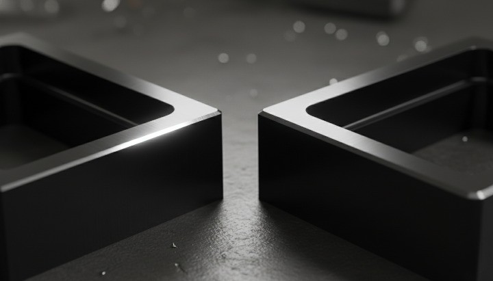
Deburring vs edge breaking vs chamfering vs polishing
Deburring focuses on removing burrs and eliminating sharpness. Edge breaking focuses on creating a small controlled edge condition that improves handling and reduces assembly damage, and it often overlaps with deburring in everyday shop language.
Chamfering creates a defined bevel with a measurable geometry, so it works well when you need repeatable assembly lead-ins or a consistent edge break you can inspect. Polishing focuses on surface texture and appearance, so it targets tool marks and roughness rather than burrs alone. Use deburring to remove unwanted material, use chamfering when you need a defined edge feature, and use polishing when surface finish drives function or cosmetics.
If you want a measurable edge break without extra manual work, a chamfer can replace “hand deburr” in many cases. That approach also makes RFQs easier to compare because every supplier quotes the same geometry and inspection intent.
Why Burrs Happen in CNC Machining?
Burrs happen because cutting does not end with a perfectly clean shear. When your tool enters or exits a surface, the material often plastically deforms, bends, or tears, and it leaves a burr behind.
Burr formation in milling, turning, drilling, threading
In turning, parting and groove exits create cut-off burrs because the tool separates the part at the end of the cut. You also see edge burrs when the insert rubs during a light finishing pass—especially on CNC turning parts.
In drilling, burrs form most aggressively on the breakthrough side. The drill loses support at exit, so the material tears instead of shearing cleanly, which creates breakout burrs around the hole—especially on CNC drilling parts.
In threading, burrs show up at thread starts, thread runouts, and hole edges. Taps can raise burrs at the entry and exit because the tool displaces material as it forms the thread profile.
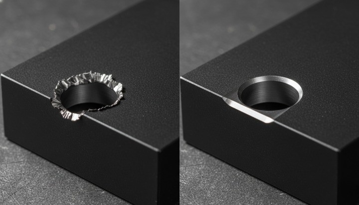
Common causes: tool wear, chip load, rigidity, exit strategy, material behavior
Tool wear increases burr risk because a dull edge ploughs instead of cutting. Researchers have reported that tool wear can increase burr size during machining, which matches what you see on real shop floors as edges lose sharpness.
Chip load and feed rate strongly influence burr formation because they change how the material deforms at the edge. One experimental study reported that feed rate had a major contribution to burr formation in its test conditions, which shows why “safe” feeds still need validation on your geometry and material.
Rigidity matters because deflection turns a clean cut into rubbing and tearing. When your workholding flexes or your tool reaches too far, the edge sees unstable cutting forces, and burrs grow faster on exits and thin walls.
Exit strategy also matters because the last millimeter of a cut often creates the burr. If you exit into open air on a thin wall, you invite rollover burrs; if you support the exit with a sacrificial tab or adjust your toolpath to reduce edge push, you usually reduce burr height.
Material behavior sets the baseline. Ductile metals tend to smear and bend, while brittle materials can chip; both behaviors can leave burr-like edge defects, just with different shapes and risks.
Burr prevention vs deburring cost: how reducing burrs lowers total cost
Deburring looks cheap until you add labor time, inspection, rework, and scrap. In industrial case studies, researchers estimated deburring costs around 2–3% of total part cost, and they also discussed deburring investment costs that can add meaningful overhead.
Other published work notes that deburring can represent a much larger share of total manufacturing costs in some settings, with reported ranges that reach into double digits depending on the part mix and process. That spread tells you one thing: deburring cost explodes when you treat burrs as an afterthought.
You can usually cut total deburring cost when you reduce burr size at the source. You do that by controlling tool sharpness, stabilizing workholding, tuning feed and exit conditions, and choosing toolpaths that avoid tearing on break-through features. Smaller burrs give you faster deburring, fewer dimensional surprises, and fewer cosmetic rejects.
Types of Burrs on Metal Parts
Burr types matter because they tell you where the burr came from and how it will behave during removal. If you name the burr correctly, you can choose a deburring method faster and protect CTQ features.
Rollover burrs, breakout burrs, tear burrs, cut-off burrs
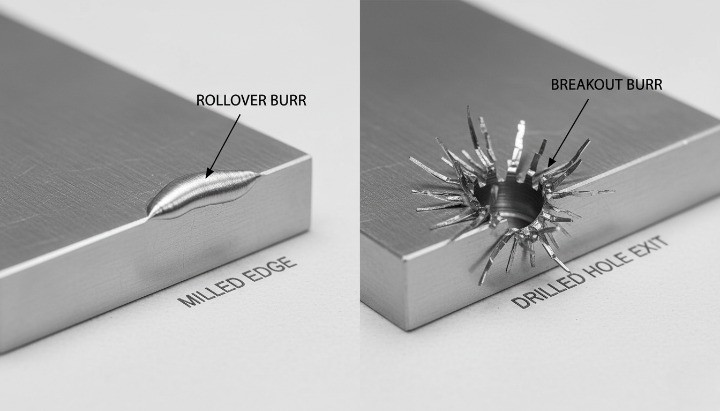
A rollover burr forms when the tool exits and pushes material over the edge instead of shearing it cleanly. You will see rollover burrs on milled edges, slot exits, and turned edges at tool exit.
A breakout burr forms when the cut breaks through and the material tears at the exit side. You often see it on drilled holes because the drill loses support at breakthrough.
A tear burr forms when material fractures or smears instead of cutting cleanly. You see it when the material stretches, when the tool dulls, or when rigidity drops and the edge starts rubbing.
A cut-off burr forms at the end of a separation cut, such as parting, sawing, or shearing. Cut-off burrs often create sharp projections that break off and contaminate assemblies.
Poisson burrs and thermal burrs
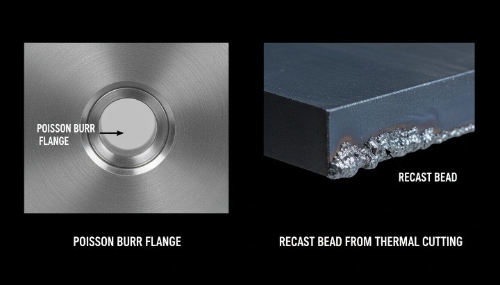
A Poisson burr forms from lateral material flow near the cut edge, driven by compression and deformation during cutting. You often see it as a thin flange-like burr along an edge, and it can be difficult to remove without changing edge geometry.
A thermal burr often shows up as a recast bead or resolidified material when a thermal process melts material and redeposits it at the edge. You should treat it differently than a mechanical burr because it can behave like hard fused material rather than a ductile lip.
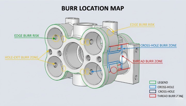
Burr locations: edges, hole exits, cross-holes, threads, pockets
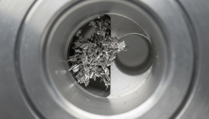
External edges and part perimeters are the easiest burr locations to spot, so teams often over-focus on them. Internal burrs create more expensive failures because they hide until assembly, leak test, or field use.
Hole exits and back-side edges create frequent breakout burrs. Cross-holes and internal intersections create burr traps because you cannot reach them easily with hand tools, and chips can cling to the burr lip.
Threads also create burr risk at the entry, the exit, and the runout. Burrs at thread starts can damage fasteners, raise assembly torque, and create false “tight” conditions during installation.
Burr severity levels and CTQ risk for functional and cosmetic parts
You should classify burr severity by what it can break, not only by how it looks. A small burr becomes CTQ when it affects fit, sealing, safety, fatigue life, cleanliness, or cosmetics.
Functional parts turn burrs into performance risk. Burrs at drilled holes can interfere with seating and can concentrate stress at edges, which can reduce fatigue resistance in service.
Cosmetic parts turn burrs into finishing risk. Sharp edges and residual burr lips can catch during handling, show through coatings, and create inconsistent edge appearance across batches. You reduce disputes when you define CTQ edges and inspection expectations early, before quoting and first articles. (source:)
How to Remove Burrs From Metal
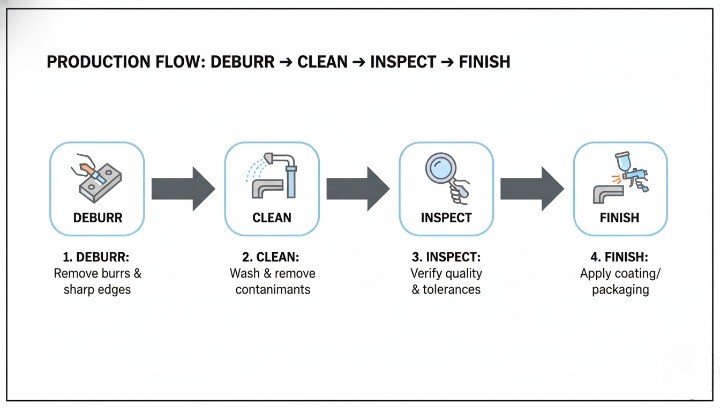
To remove burrs from metal parts, you need a repeatable flow that covers edge removal, cleaning, and verification. A practical CNC deburring workflow is: machine the part, remove burrs with a defined method, clean the part, inspect CTQ edges and hidden features, then apply finishing and perform final inspection. Burrs exist in many shapes and locations, so you should match the method to the risk, not to habit.
Deburring costs can become a major cost driver when teams treat it as “minor cleanup.” Some manufacturing references estimate manual deburring can reach about 30% of total part cost in certain cases, especially when parts are small or edges are hard to access.
Deburring process flow: machine, deburr, clean, inspect, finish, final check
You can run deburring like a controlled process instead of a loose “bench step.” The goal is consistent edges, consistent cleanliness, and consistent inspection results across batches.
| Step | What you do | What you control | What you record |
|---|---|---|---|
| Machine | Cut features with stable parameters | Burr size at the source | Tool life, key parameters |
| Deburr | Apply the chosen deburring method | Edge condition and burr removal | Method, tools, settings |
| Clean | Remove chips and abrasive residue | Particle and media carryover | Cleaning method, time |
| Inspect | Verify edges and hidden burr traps | CTQ edges, hole exits, threads | Criteria + sampling |
| Finish | Anodize, plate, paint, polish if needed | Edge appearance and coating behavior | Finish spec + handling |
| Final check | Confirm packaging-ready condition | Cosmetic edges, cleanliness, count | Final inspection results |
If you want your RFQs to stay stable, you should define the deburring step as part of the process route, not as an optional instruction at the end. You can align this with your QC flow and inspection expectations.
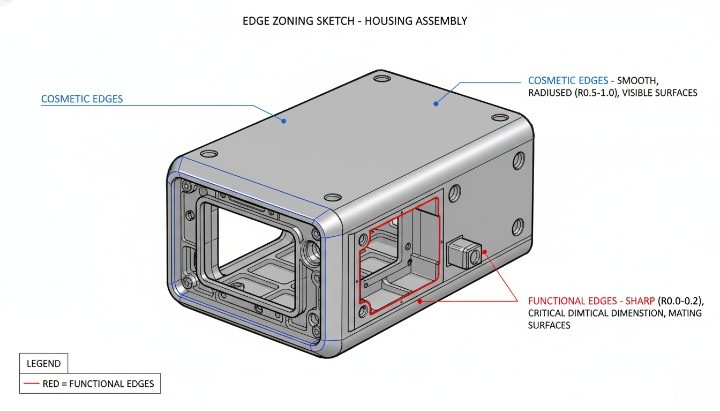
Quality targets: edge break, no-burr zones, cosmetic vs functional edges
You get better outcomes when you define what “good” looks like. Deburring quality targets should name the edge intent and the risk zones, so suppliers do not guess.
Use these targets as a practical structure:
-
Edge break requirement for general edges that people handle or assemble
-
No-burr zones for features that can fail from tiny burrs, such as hole exits, ports, sealing faces, threads, and cross-hole intersections
-
Cosmetic edge rules for visible surfaces and touch points
-
Functional edge rules for datums, fits, sealing, and fatigue-sensitive edges
If you do not want to fully define a chamfer geometry, you can use a standardized approach for undefined edges. ISO 13715 specifies rules for indicating and dimensioning edges of undefined shape, which helps teams communicate edge condition intent more consistently.
Cleaning and contamination control after deburring
Deburring often creates its own contamination risk. Abrasive media, brush filaments, loose chips, and broken burr fragments can remain inside pockets and cross-holes.
If your part controls flow, seals, electronics, or moving interfaces, you should treat cleanliness as part of the deburring outcome. Industry cleanliness frameworks define cleaning as the removal of particulate contaminants and describe how teams document cleanliness inspection.
You can apply a simple “cleanliness escalation” logic:
-
Standard parts: blow-off + wash + dry, then visual checks
-
Fluid or sealing parts: controlled wash + filtered rinse, then particle checks on risk features
-
High-risk applications: cleanliness specification and inspection aligned to recognized methods for particulate contamination assessment
If you plan anodizing or plating, cleaning matters even more because residue and trapped chips can show up as cosmetic defects or coating anomalies during finishing.
How deburring changes dimensions and tolerances?
Deburring removes material, so it can change dimensions near edges. Any method that rounds, chamfers, or abrades can reduce edge sharpness and can shift local geometry, which matters when you control fits, sealing faces, or datum edges.
These are the common tolerance risks you should manage:
-
Edge radius growth that reduces effective wall thickness
-
Chamfer size variation that changes assembly lead-in behavior
-
Thread start damage that affects gauge results and torque
-
Bore edge rounding that affects sealing, O-rings, or press fits
You reduce dimensional surprises when you do two things:
-
You specify edge intent where it matters instead of using a global “deburr all edges” note
-
You choose a deburring method that matches the tolerance sensitivity of nearby features
If the part has tight tolerances near an edge, you should treat deburring like a controlled machining feature, not a manual finishing step.
Deburring inspection and acceptance criteria
Inspection must match the failure mode. A burr that cuts hands is obvious. A burr that causes leaks or contamination often hides until the worst moment.
A strong acceptance plan checks the right locations with the right method:
-
Visual inspection with edge zoning and a reference sample
-
Touch checks only where they make sense, not as the main standard
-
Borescope checks for cross-holes and internal intersections
-
Thread gauges and torque feel checks for threaded features
-
Cleanliness inspection steps when particulate contamination affects function
You will prevent most disputes when you align three items:
-
Edge requirement on the drawing
-
Deburring method in the process route
-
Inspection method and sampling plan tied to CTQ edges
If you want a supplier to quote and control deburring properly, you should ask them to state the planned method and the inspection approach for hole exits, cross-holes, and threads—supported by a defined quality control workflow.
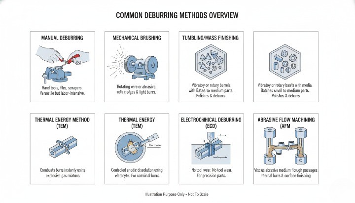
You can remove burrs with six practical method families: manual, in-machine mechanical, brush deburring, mass finishing, abrasive blasting, and advanced processes like thermal deburring and electrochemical deburring for internal burrs. The right choice depends on burr location, tolerance sensitivity, cleanliness risk, and batch volume.
| Method | Best for | Hidden burrs | Dimensional risk | Typical fit |
|---|---|---|---|---|
| Manual deburring | Prototypes, mixed parts, quick fixes | Limited | Medium | Low volume |
| In-machine deburring toolpaths | Repeatable external edges | Limited | Low to medium | Prototype to production |
| Brush deburring | Cross-holes, intersections, controlled edge break | Medium | Low | Low to medium volume |
| Mass finishing | Batch edge conditioning | Low to medium | Medium | Medium to high volume |
| Abrasive blasting | Light burrs, cosmetics, surface prep | Low | Low to medium | Low to medium volume |
| Thermal + electrochemical | Hard-to-reach internal burrs | High | Low to medium | Medium to high volume |
Method 1: Manual deburring tools and best-fit use cases
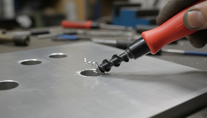
Manual deburring removes burrs with hand tools or handheld power tools, and it fits prototypes, small batches, and mixed part families. Wikipedia lists manual deburring as the most common process because it stays flexible and uses low-cost tools.
I use manual deburring when the part mix changes daily or when the burrs vary across setups. Manual work lets you target the exact edge that matters, but it also increases variation from operator to operator.
Use manual deburring when you need speed and flexibility.
-
You run prototypes or very low volume parts.
-
You need selective touch-up on a few edges.
-
You want instant visual verification before shipping.
Avoid manual deburring when you need repeatability at scale.
-
You have CTQ edges near tight tolerances.
-
You have cross-holes or internal intersections.
-
You need documented, stable outputs across shifts.
Method 2: Mechanical deburring in CNC with chamfer toolpaths
In-machine deburring uses CNC toolpaths to create a controlled edge break, often with chamfer tools, ball end mills, or spot drills. CAM systems can generate deburr toolpaths by selecting edges and applying a target edge condition.
I like in-machine deburring because it turns a subjective bench step into a measurable machining feature. You get more consistent edges, fewer handling marks, and fewer quote swings when you specify the edge intent.
In-machine deburring fits best when you can access the edge.
-
External perimeters and open pockets
-
Counterbores and spotfaces
-
Thread starts and hole entries you can reach in the same setup
You should watch two failure modes.
-
Tool reach and collision risk can force extra setups.
-
A “light” chamfer can still change fit if the edge sits next to a datum or sealing face.

Method 3: Brush deburring for cross-holes and internal intersections
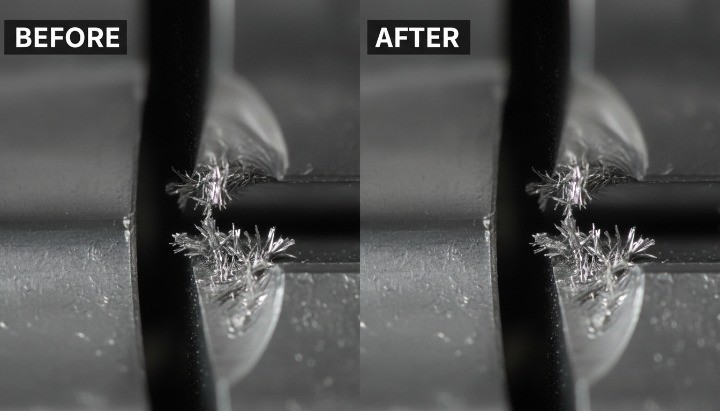
Brush deburring uses abrasive or filament brushes to remove light burrs and blend edges, and it performs well on intersections like cross-holes. Cross-hole deburring often needs specialized access because the burr sits at an internal intersection.
I use brush deburring when I want a controlled edge break without aggressive material removal. Brushes can also reduce the risk of gouging compared with hard cutting tools on awkward features.
Brush deburring fits these scenarios.
-
Cross-holes and internal intersections
-
Ports and fluid passages that need a blended edge
-
Parts that need consistent “break sharp edges” without a defined chamfer
You still need a residue plan. Brushes shed wear debris, and internal burr traps can hold chips. You should pair brush deburring with cleaning that matches your contamination risk.
Method 4: Mechanical deburring with mass finishing and vibratory tumbling
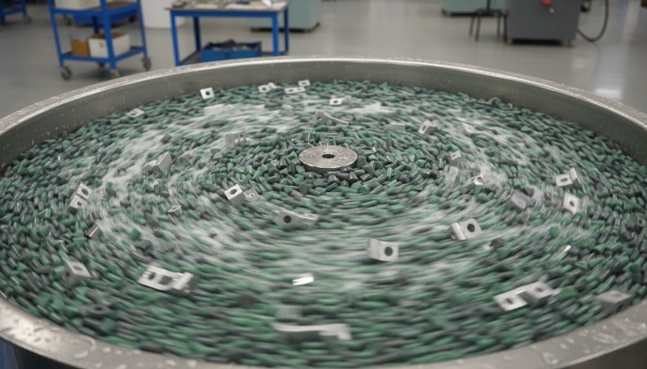
Vibratory finishing is a mass finishing process that uses vibration to move parts, media, and compound together to deburr and finish surfaces. ScienceDirect describes it as an automated process that deburrs by oscillation or vibration, and it commonly supports batch processing.
I recommend mass finishing when you need uniform edge conditioning across a batch of small to mid-size parts. You can deburr many parts at once, but you must control edge radius growth and protect sensitive features.
Mass finishing works best for:
-
Medium to high volume batches
-
Parts that tolerate slight edge rounding
-
Parts that need consistent “softened” edges for handling
Mass finishing creates risk for:
-
Threads, sharp functional edges, sealing faces
-
Tight bores and bearing seats
-
Thin walls that can ding or peen during tumbling
Method 5: Abrasive blasting deburring and masking rules
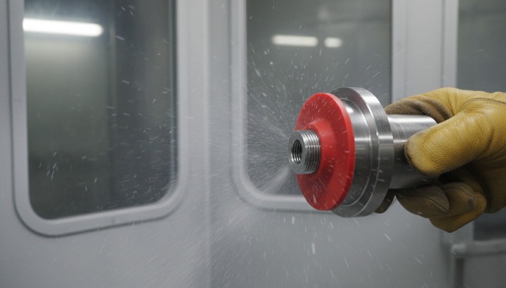
Abrasive blasting can remove light, brittle burrs and improve surface uniformity, but it rarely removes heavy burrs without risk. Microblasting with glass bead often targets fine rollover burrs and can produce minimal edge break when you tune pressure and media.
I use blasting when cosmetics matter or when I need light burr removal on accessible edges. I always plan masking, because blasting can damage threads, alter sealing faces, and leave media in pockets.
Use blasting when:
-
You have fine burrs and cosmetic blending needs
-
You want surface prep for coating
-
You can fully control masking and cleaning
Mask these areas by default:
-
Threads, precision bores, sealing faces, datums
-
Deep pockets and cross-holes that can trap media
Method 6: Thermal deburring and electrochemical deburring for internal burrs
Thermal deburring and electrochemical deburring target hard-to-reach burrs, especially at internal intersections like cross-holes. Wikipedia describes electrochemical deburring as dissolving burrs with an electrolyte and electricity, and it notes fast cycle times for precision edges.
Thermal Energy Method deburring ignites a combustible gas mixture in a chamber and preferentially burns thin burrs due to their high surface-area-to-mass ratio. ScienceDirect describes TEM as a chamber-based process that deburrs by igniting a volatile gas mixture around the workpiece.
Electrochemical deburring focuses removal at the burr region through current density concentration. A peer-reviewed MDPI study discusses how current density near a burr tip drives preferential removal, which supports why ECD works well for intersections.
I choose between thermal and electrochemical based on three practical factors.
-
I choose thermal when I need to remove many internal burrs at once.
-
I choose electrochemical when I need controlled removal at a specific intersection edge.
-
I plan cleaning and verification either way, because internal processes can leave oxide, residue, or trapped debris if teams skip post-process controls.

Deburring Method Selection Guide
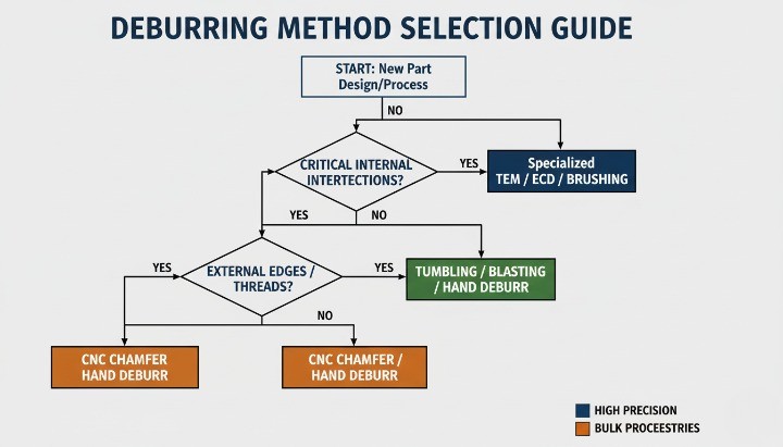
Choose a deburring method by burr location first, then validate it against material, volume, and tolerance risk. External edges usually allow manual or in-machine deburring, while cross-holes and internal intersections often need brush tools, thermal deburring, or electrochemical deburring for reliable burr removal.
Choose by burr location: edges, hole exits, cross-holes, threads
Location drives access, and access drives method. If you cannot reach the burr, you cannot control quality with “hand deburr” language.
Use this location-first guidance:
-
External edges and open pockets: manual, in-machine chamfer toolpaths, light blasting
-
Hole exits and back-side edges: in-machine chamfer, manual, brush, selective mass finishing
-
Cross-holes and internal intersections: brush tools, thermal deburring, electrochemical deburring
-
Threads and thread runouts: in-machine edge cleanup, controlled manual, avoid aggressive tumbling
-
Deep pockets and hidden cavities: brush, thermal, electrochemical, plus strong cleaning controls
Choose by material: aluminum, stainless steel, carbon steel
Material changes burr behavior and also changes how safe each method feels. Ductile materials often smear and bend, while harder materials can leave sharper burrs that break off as debris.
Practical material rules that help sourcing:
-
Aluminum: favor in-machine deburring and light brushing to keep geometry stable
-
Stainless steel: plan for tougher burrs and higher cleaning expectations, and avoid uncontrolled hand work on CTQ edges
-
Carbon steel: manage sharp burrs and corrosion-sensitive burr traps, then confirm coating and cleanliness intent
If your part has a coating or finish, you should align method choice with finishing risk. Burrs and rough edges can create coating thickness variation and cosmetic edge defects, so the “right” deburring method often depends on what happens after deburring.
Choose by volume: prototype, low volume, mass production
Volume determines whether flexibility or repeatability matters more. Manual deburring stays common because it is flexible and allows instant inspection, but it becomes hard to control at scale.
A simple volume-based approach works well:
-
Prototype: manual plus selective in-machine deburring for critical edges
-
Low volume: in-machine deburring for repeatability, manual only for touch-up
-
Mass production: mass finishing, brush systems, or advanced processes, with defined inspection and cleanliness controls
If you need fast internal burr removal at scale, thermal deburring can remove burrs across many surfaces at once, while electrochemical deburring can target intersecting holes precisely.
Choose by tolerance risk: where over-deburring causes scrap
Deburring removes material, so it can change edge geometry. You should treat deburring like a controlled feature when the edge sits near a datum, a sealing face, a press fit, or a critical bore.
High tolerance risk zones include:
-
Bearing seats and tight bores
-
Sealing faces and O-ring glands
-
Datum edges that drive alignment
-
Thread starts and runouts that must gauge cleanly
If you have high tolerance risk, avoid uncontrolled methods that round everything. Mass finishing and aggressive blasting can soften edges beyond what you expect, so you should reserve them for parts that tolerate edge radius growth.
When you need a measurable outcome, you can specify edge condition instead of using a vague note. ISO 13715 defines rules for indicating and dimensioning undefined edges, which helps you control interpretation across suppliers.
Deburring decision matrix: scenario to recommended method
Use this matrix to pick a starting method, then validate it with your CTQ list and cleaning plan.
| Scenario | Burr location | Volume | Tolerance risk | Recommended method |
|---|---|---|---|---|
| Prototype brackets, visible edges | External edges | Low | Low | Manual + light in-machine edge break |
| CNC housings with cosmetic faces | External edges, pockets | Low–mid | Medium | In-machine chamfer toolpaths + controlled handling |
| Drilled plates with backside burrs | Hole exits | Low–mid | Medium | In-machine chamfer or spotface + manual verify |
| Manifolds with cross-holes | Cross-holes | Mid–high | Medium | Brush tools, or thermal deburring for many intersections |
| Precision intersecting holes | Intersections | Mid–high | High | Electrochemical deburring for targeted removal |
| Small parts needing uniform edge softening | Mixed edges | High | Low–medium | Mass finishing with controlled media and time |
| Parts requiring surface prep before coating | Accessible edges | Low–mid | Low–medium | Abrasive blasting with masking and strong cleaning |
| Threaded parts with gauge requirements | Threads | Any | High | In-machine edge cleanup + controlled manual touch-up |
If you want stable quotes and stable quality, ask the supplier to name the planned deburring method for each CTQ zone and to state how they will inspect hole exits, cross-holes, and threads as part of their overall manufacturing capability and process control.
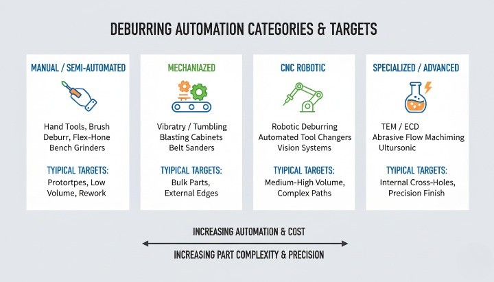
Manual deburring stays flexible, but it rarely stays consistent at scale. When your deburring time becomes unpredictable, automation often becomes the cheapest way to stabilize quality, lead time, and total cost. A NIST report notes that manual deburring can reach up to 30% of total part cost in some cases, which explains why many manufacturers invest in deburring automation when volumes grow.
When manual deburring stops scaling?
Manual deburring stops scaling when your output depends on individual technique rather than a controlled process. The same NIST report highlights how manual deburring quality and output rate can vary widely, which creates unstable production planning.
You should treat these as “automation triggers” in CNC deburring.
-
Your deburring time per part swings by more than 2× across operators or shifts.
-
You see recurring internal burr escapes at hole exits or cross-holes.
-
You keep reworking cosmetic edges after anodizing or plating.
-
You cannot define acceptance without “feel” or “shop judgment.”
Deburring also becomes an automation candidate when cost share rises. A published industrial case-study assessment estimated deburring costs around 2–3% of total part cost in its sample, but other research reports higher ranges depending on process and part mix.
Deburring machine categories: mass finishing, brush systems, thermal, electrochemical
Choose the machine category by access and burr type, not by brand or machine size. If the machine cannot reach the burr, it cannot guarantee burr-free parts.
Mass finishing systems remove burrs in bulk. Vibratory finishing is commonly described as a mass finishing process that uses oscillation or vibration to deburr and finish parts in an automated setup.
Brush systems target edges and intersections with controlled contact. They work well when you need repeatable edge breaking on external edges and predictable deburring at some internal features, especially when you combine them with good fixturing and cleaning.
Thermal Energy Method deburring removes hard-to-reach burrs across multiple surfaces at once by igniting a gas mixture in a pressurized chamber. Sources describe TEM as a chamber process that ignites a volatile gas mixture to deburr components.
Electrochemical deburring uses electrochemical machining principles to remove burrs selectively. Wikipedia notes ECM is widely used as a deburring process because it removes metal projections left from machining and dulls sharp edges.
Automation risks: dimensional change, residue, cosmetic damage
Automation reduces labor variation, but it can introduce new failure modes. You should manage automation risk the same way you manage machining risk: define CTQ zones, control inputs, and verify outputs.
Dimensional change happens when the method rounds edges more than you expect. Mass finishing can increase edge radius over time, so you must control media, cycle time, and part-to-part contact.
Residue risk rises when media, oxide, or debris remains inside pockets and cross-holes. Thermal deburring and mass finishing can leave residue that you must remove with a defined cleaning process, especially for fluid, sealing, or electronics-adjacent parts.
Cosmetic damage shows up as dings, peening marks, or inconsistent edge appearance. Automation can worsen cosmetics when parts contact each other in bulk, or when handling after deburring lacks protection.
What to ask a supplier about automation capability
Ask questions that force a process answer, not a marketing answer. You want the supplier to state method, controls, and verification.
Use this checklist during RFQ review:
-
Which deburring method will you apply to each CTQ zone, especially hole exits, cross-holes, and threads?
-
How will you control edge condition so it stays inside my tolerance risk limits?
-
What cleaning process will you use to remove media, oxide, and trapped debris after deburring?
-
What inspection method will you use for internal burr traps, and what sampling plan will you follow?
-
If you use TEM or electrochemical deburring, how will you verify that the main surfaces stay unaffected?
-
Can you provide first-article evidence for burr-free requirements on cross-holes and thread starts?
Deburring Specs for RFQ and Drawings
Good deburring specs remove guesswork. When you define edge intent, you stabilize quotes, reduce rework, and prevent “burr-free” disputes at first article.
Why “deburr all edges” creates ambiguity
A burr is a raised edge or small piece of material left after machining, and teams remove it through deburring. That definition sounds clear, but “deburr all edges” still forces interpretation.
One supplier may do a light edge break. Another may add a visible radius. Both suppliers can claim they “deburr,” and your assembly may still fail.
You eliminate ambiguity when you specify where burrs are unacceptable and what edge condition you want. ISO 13715 exists for this reason, because it defines rules for indicating and dimensioning undefined edges.
Better callouts: edge break range, chamfer size, no-burr CTQ zones, surface zoning
Start with four building blocks. You can mix them across zones. This approach helps you protect CTQ features without over-specifying every edge.
| Callout type | What it controls | Where it works best | Typical risk if missing |
|---|---|---|---|
| Edge break range | Small controlled edge condition | General handling edges | Sharp edges, inconsistent feel |
| Chamfer size | Defined bevel geometry | Assembly lead-ins, deburr-by-machining | Tolerance and fit variation |
| No-burr CTQ zone | Burr not allowed in a defined area | Sealing, flow, threads, sensors | Leaks, contamination, false fits |
| Surface zoning | Different rules by surface class | Cosmetic vs functional separation | Cosmetic disputes, overwork |
If you do not want a defined chamfer, you can specify an undefined edge condition using ISO 13715. ISO 13715 specifies rules for indicating and dimensioning edges of undefined shape on technical documentation.

Copy-paste deburring notes for drawings and RFQs
Use these notes as a starting point, then adjust them to your CTQ list. Keep notes short, measurable, and zone-based.
-
General note for most CNC parts Break sharp edges 0.2–0.5 mm unless otherwise specified. Remove all loose burrs.
-
CTQ no-burr zones for functional edges No burrs permitted on sealing faces, gasket lands, bearing seats, and datum edges.
-
Internal intersections and cross-holes No burrs permitted at cross-hole intersections and internal ports. Supplier must verify burr removal by borescope or equivalent method.
-
Cleanliness-sensitive parts After deburring, clean to remove chips, abrasive residue, and loose particles from pockets, holes, and internal passages.
-
Cosmetic surfaces and handling protection Cosmetic surfaces A must be free of sharp edges, tool tears, and handling scratches. Package to protect burr-free edges.
Hole and thread deburring requirements for production parts
Holes and threads fail quietly when deburring stays vague. A small exit burr can cut an O-ring, block a flow path, or create false seating.
Use feature-level rules where you see repeat failures:
-
Drilled hole exits: no breakout burrs; apply controlled edge break on entry and exit
-
Cross-holes: no burrs at intersections; verify with borescope on first article
-
Threads: no burrs at thread start and runout; threads must pass gauge after deburring
-
Tapped holes: remove entry/exit burrs without rolling material into the first thread
If you plan anodizing or plating, define edge intent before finishing. Finishing can highlight edge defects and make disputes harder to solve later.
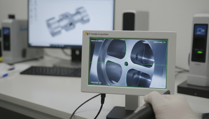
Inspection method and sampling plan
Inspection must match the burr risk. You will miss internal burrs if you only check external edges. You also create waste if you inspect everything at the same level.
A practical inspection structure looks like this:
-
First article: inspect all CTQ zones, including cross-holes and thread starts
-
Production: sample general edges, but keep higher checks on high-risk features
-
Internal burr traps: use borescope or magnified visual checks when access is limited
-
Threads: use thread gauges and verify thread starts and runouts visually
Record three items in your control plan: the edge requirement, the deburring method, and the inspection method. When these three match, you get stable burr-free output across batches.
Common Deburring Problems and Solutions
Most deburring problems come from one root issue: teams treat deburring as “cleanup” instead of a controlled process. You fix recurring deburring failures when you link the burr risk to an edge spec, a method, and an inspection step.
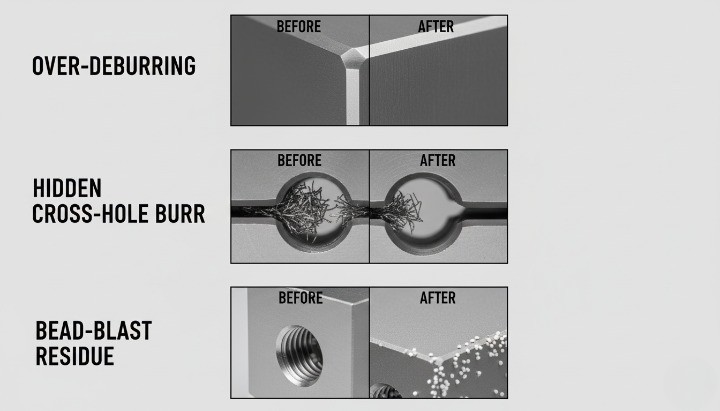
Over-deburring and tolerance loss
Over-deburring removes more material than you planned, so you lose edge geometry and sometimes distort thin sections. A machining study notes that many mechanical deburring methods change part dimensions slightly and mechanical forces can distort thin sections.
You usually see over-deburring in these situations:
-
You deburr by hand near datums, sealing faces, and press fits
-
You tumble parts that have tight edge requirements
-
You brush threads aggressively, then gauges start failing
Use these controls to prevent scrap:
-
Replace vague notes with measurable edge intent on CTQ edges
-
Use in-machine edge breaks where you can, because you control geometry
-
Set a hard limit for edge break near fits and sealing faces, then inspect it
Hidden burrs causing leaks, contamination, assembly damage
Hidden burrs create the most expensive failures because they escape visual checks and show up during assembly, leak testing, or field use. In fluid power and motion control, deburring guidance warns that burrs can create friction, come loose, and score or damage other components.
Cross-holes and internal intersections are high-risk burr traps. A research paper on cross-drilled holes notes burrs can block critical passages and contribute to leakage or failure in valves.
You reduce hidden-burr escapes when you do three things:
-
You treat cross-holes as CTQ zones and select a method designed for access
-
You verify internal intersections with borescope or equivalent checks on first article
-
You add a cleaning step that targets internal passages, not just external surfaces
Trapped media after mass finishing and blasting
Mass finishing and blasting improve throughput, but they can leave residue behind. A mass finishing reference calls media lodgment a major hazard because media can lodge in features even when you classify and separate media after processing.
Vibratory finishing references also note that small holes, slots, and undercuts can trap media and may require manual cleaning.
Use these solutions when you see trapped media:
-
Choose media size and shape that cannot enter your smallest features
-
Add feature-level masking or plugs where blasting can drive media into cavities
-
Define a post-process cleaning method and verification step for burr traps
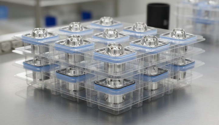
Cosmetic defects from handling after deburring
Deburring often improves safety and feel, but poor handling can destroy cosmetics afterward. Your team may remove burrs perfectly, then add scratches or edge dings during bench work, washing, or packaging.
You prevent cosmetic damage with process discipline:
-
Separate cosmetic surfaces from functional surfaces using surface zoning
-
Use trays, separators, or protective wraps right after deburring
-
Train operators to avoid stacking and sliding parts edge-to-face
Finishing conflicts: anodizing and plating highlighting edge defects
Finishing can reveal defects that you did not notice before. A technical article on anodizing explains that surface defects can become visible after anodizing even if they were not visible before treatment.
You can avoid finishing disputes when you align deburring and finishing intent:
-
Deburr before anodizing or plating with a defined edge rule for cosmetic edges
-
Keep burr traps clean so residue does not show up as staining, pits, or edge artifacts
-
Protect edges during racking, transport, and post-finish handling
Repeatable Deburring Workflow for Production
A repeatable deburring workflow turns “burr-free” from a subjective promise into a measurable output. I recommend you lock three things together: CTQ edge zones, a defined deburring method per zone, and a verification step that matches the risk. When these three match, your quotes stabilize and your rejects drop.
Control points for CTQ edges, hole exits, threads, sealing faces
Start by marking where burrs can cause functional failure. External edges matter, but CTQ zones usually sit at interfaces like seals, threads, and flow paths.
Use this CTQ checklist during DFM and RFQ review:
-
Sealing faces and O-ring glands
-
Bearing seats and press-fit bores
-
Datum edges that drive alignment
-
Hole exits and cross-hole intersections
-
Thread starts, runouts, and counterbores
Then assign a control point to each CTQ zone. I prefer you define “what” you accept, “how” you remove burrs, and “how” you verify it.
| CTQ zone | Typical burr risk | Preferred control | Verification |
|---|---|---|---|
| Hole exits | Breakout burr lip | In-machine edge break or controlled tool | Visual + go/no-go fit check |
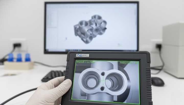
| Cross-holes | Hidden intersection burr | Brush, thermal, or electrochemical | Borescope on first article |
| Threads | Burr at start/runout | In-machine cleanup + light hand touch | Thread gauge + visual start check |
| Sealing faces | Micro-burr cuts seals | Minimal edge break, strict handling | 100% visual on CTQ face |
| Datums | Edge damage shifts alignment | Controlled edge rule | First-article dimensional review |
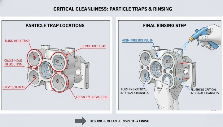
Cleaning steps and particle control
Deburring creates particles, loose burr fragments, and sometimes abrasive residue. If you ignore cleaning, you can ship “burr-free” parts that still fail due to contamination.
For parts used in fluid, sealing, or precision assemblies, I recommend you align cleaning and inspection with recognized technical cleanliness frameworks. ISO 16232 covers methods and documentation for determining particulate contamination on functionally relevant components. VDA 19.1 also focuses on inspection of technical cleanliness for functionally relevant parts.
Use a simple, scalable cleaning ladder:
-
Standard parts: rinse or wash, blow-off, dry, then visual checks
-
Internal passages: focused flushing, filtered rinse, controlled drying
-
High-risk systems: documented particle inspection approach aligned to ISO 16232 or VDA 19.1 requirements
Deburring before anodizing, plating, painting, and assembly
Finishing does not hide edge defects. It often makes them easier to see, especially on aluminum parts after anodizing.
Hydro explains that surface defects can become visible after anodizing because pre-treatment and oxide growth can reveal underlying surface conditions. A finishing guide also notes that anodising will not hide pre-existing defects like scratches or embedded debris, so surface preparation and edge control matter.
Deburr before finishing, then protect edges through transport and racking. This order reduces cosmetic rejects and prevents coating-related disputes.
Use these finishing alignment rules:
-
Anodizing: control cosmetic edges and avoid handling marks before racking
-
Plating: remove burrs that trap solution and create edge artifacts
-
Painting: remove sharp edges that lead to thin coating and early wear
-
Assembly: confirm burr-free hole exits, threads, and sealing surfaces before build
Packaging to protect burr-free cosmetic edges
Deburring makes edges safer, but packaging keeps them burr-free during shipping. Most cosmetic damage happens after deburring when parts rub or impact each other.
For heavier components, shipping guidance recommends bracing and securing parts to prevent damage during handling. Packaging manuals also emphasize securing loads and using clear handling instructions to reduce transit damage.
Use packaging that blocks metal-to-metal contact:
-
Individual bags or wraps for cosmetic parts
-
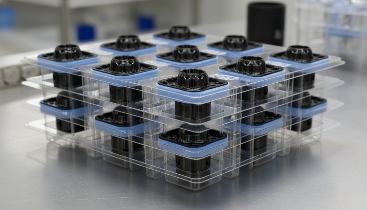
Separator trays with compartments for repeatable positioning
-
Foam or corrugated separators for mixed geometry loads
-
Pallet strapping and bracing for heavy parts
[Add image here: compartment tray packaging for anodized housings.] Alt text: Separator tray packaging to protect burr-free cosmetic edges on CNC machined parts
Buyer’s RFQ Checklist
A strong deburring RFQ reduces quote variation and prevents first-article surprises. I recommend you package files, edge intent, and inspection expectations so every supplier quotes the same risk and the same work.
Files: 2D, 3D, CTQ list, edge zones, finish requirements
Send one RFQ bundle that a supplier can execute without guessing. Keep names consistent across files and revisions.
| Item | What to include | Why it matters for CNC deburring |
|---|---|---|
| 2D drawing | GD&T, datums, hole notes, thread callouts | Deburring must not damage datums, fits, or seals |
| 3D model | STEP preferred, latest revision | Helps plan tool access and in-machine deburring |
| CTQ list | CTQ features and CTQ edges | Focuses inspection on the burr traps that cause failures |
| Edge zones | Mark A/B/C surfaces and “no-burr zones” | Prevents “deburr all edges” interpretation |
| Finish requirements | Anodizing, plating, paint, texture targets | Finishing amplifies edge defects and residue risk |
| Application notes | Sealing, fluid path, sensor areas, clean parts needs | Drives method choice for cross-holes and intersections |
Supplier questions: method, dimensional protection, cleaning, inspection plan
Ask questions that force a process answer. You want method, controls, and verification tied to CTQ zones.
Use this checklist in your RFQ email or RFQ form:
-
Which deburring method will you use for each edge zone and each CTQ feature?
-
How will you deburr hole exits, cross-holes, and internal intersections?
-
How will you protect tolerances near datums, sealing faces, and press fits?
-
What cleaning steps will you use to remove chips and residue after deburring?
-
How will you inspect internal burr traps, and what tools will you use?
-
What sampling plan will you follow for CTQ edges during production?
Quote format: deburring method, cycle time, quality scope
You should request a quote that separates deburring work and inspection scope. This format makes supplier offers comparable and reduces change orders later.
| Quote line item | What the supplier should state | What you compare |
|---|---|---|
| Deburring method by zone | Manual, in-machine, brush, mass finishing, blasting, thermal, electrochemical | Method fit for access and CTQ risk |
| Process steps | Where deburring sits in the route | Handling and defect risk across steps |
| Cycle time impact | Estimated added time per part or per batch | True total cost, not hourly rate |
| Cleaning scope | Wash, flush, filtered rinse, drying | Residue control for internal passages |
| Inspection scope | CTQ checks, internal checks, thread gauging | Risk coverage and consistency |
| First-article deliverables | Photos of CTQ zones, borescope evidence if needed | Fast approval and fewer disputes |
FAQs
What is deburring in machining?
Deburring is the process of removing burrs from a machined part so edges meet the required condition. A burr is a raised edge or small piece of material that remains after machining operations like drilling, milling, and turning.
In production, “deburr” should mean more than “make it feel smooth.” You get repeatable results when you define where burrs are unacceptable and what edge break you allow.
How to remove burrs from metal parts after CNC machining?
Start with a zone-based process: remove burrs with the right method, then clean, then verify. Burr removal without cleaning and inspection often creates hidden escapes, especially in cross-holes and threads.
A practical approach by feature:
-
External edges: in-machine chamfer toolpaths or controlled manual deburring
-
Hole exits: controlled edge break on entry and exit, then verify
-
Cross-holes: brush tools, thermal deburring, or electrochemical deburring, then borescope check
Does deburring change dimensions and tolerances?
Yes. Deburring removes material, so it can change edge geometry and affect tight fits, sealing faces, and datum edges. This risk increases when you tumble parts, blast aggressively, or hand-deburr next to CTQ features.
To control tolerance risk, do these steps:
-
Specify edge intent on CTQ edges instead of using “deburr all edges”
-
Use in-machine edge breaks where you need repeatable geometry
-
Limit mass finishing to parts that tolerate edge radius growth
Deburring vs chamfering for drawings?
Deburring removes unwanted burrs. Chamfering defines a measurable bevel feature. If you need a consistent, inspectable edge condition, a chamfer callout often communicates intent better than “deburr.”
Best deburring methods for stainless steel?
Stainless steel can form stubborn burrs because many stainless grades work-harden during machining, so burrs can become tougher than you expect.
A practical stainless strategy is:
-
Prefer controlled in-machine edge breaks for accessible edges
-
Use brush deburring for intersections when you need consistent edge conditioning
-
Use electrochemical or thermal deburring for hard-to-reach internal burrs, then verify and clean
How to deburr cross-holes and internal intersections?
Cross-holes almost always create burrs at the intersection, and access limits make them difficult. That is why many manufacturers use specialized approaches for intersecting holes, including electrochemical deburring and other dedicated methods.
Use a rule that matches risk:
-
Low risk: brush tools + borescope check on first article
-
Higher risk: electrochemical deburring for targeted removal or thermal deburring for many internal burrs, then cleaning + verification
What is the difference between deburring and edge breaking?
Deburring focuses on removing burrs that remain after machining. Edge breaking focuses on creating a small controlled edge condition so the part is safe to handle and assembles consistently. In practice, many shops combine both goals in one step.
If you need consistent interpretation across suppliers, specify the edge condition on the drawing instead of relying on a general note. ISO 13715 supports this by standardizing how teams indicate undefined edge conditions.
How do I specify no burrs on hole exits and threads?
Do not rely on “deburr all edges.” Define no-burr CTQ zones and call out hole exits and thread starts explicitly. ISO 13715 helps when you want a controlled edge condition without defining a full chamfer geometry.
Use feature-focused language:
-
Hole exits: No burrs permitted on entry and exit. Controlled edge break required.
-
Cross-holes: No burrs permitted at intersections. Verify by borescope on FAI.
-
Threads: No burrs at thread start/runout. Threads must pass gauge after deburring.
Conclusion
Best method by burr type, location, and volume
Pick your deburring method by burr location first, then confirm it against tolerance risk and volume. Use in-machine edge breaks for accessible edges, add brush deburring for intersections, and use thermal or electrochemical deburring when internal burrs hide in cross-holes. For scaling decisions, NIST notes manual deburring can reach 30% of total part cost, which explains why automation often becomes the stability play in production.
If you want fewer quote swings and fewer burr-related escapes, send your 2D/3D files plus your CTQ edge zones and finish requirements. HM can recommend a deburring method per zone, define inspection checks for hole exits and cross-holes, and align cleaning before anodizing or plating.