
Fillet vs. Chamfer in CNC Machining: Practical Edge Design Decisions for Engineers
Choosing between a fillet vs chamfer shapes strength, cost, and manufacturability.
Many teams treat edge details as “finish work,” then they wonder why quotes vary, deburring grows, or fatigue failures show up in testing. In CNC machining, a small radius or a simple chamfer can change tool access, cycle time, inspection effort, and even how suppliers price risk.
In this guide, you will learn how engineers pick the right edge for function and production, how to specify edges cleanly on drawings and RFQs, and how to avoid over-specs that quietly raise cost without improving performance.
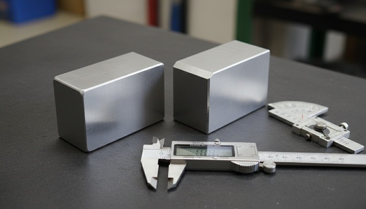
Why Edge Design Matters More Than Most Engineers Expect?
Edge design matters because it controls stress behavior, assembly fit, safety, and manufacturing risk in one small feature. When you pick the wrong edge type—or you specify it poorly—you often pay twice: once in machining time and again in rework, deburring, or inconsistent quality.
In practice, edges touch almost everything you care about in production: tools, fixtures, finish, inspection, handling, and supplier assumptions.

Edge Features Are Functional, Not Cosmetic
Engineers use edges to solve real problems, not to “make parts look nice.” You can treat an edge as a functional feature when it changes performance at the interface.
-
Stress concentration and fatigue behavior A sharp corner concentrates stress. A fillet can reduce that concentration and extend fatigue life.
-
Assembly guidance and part alignment A chamfer often acts like a lead-in. It helps pins, shafts, screws, and mating parts find their way.
-
Operator safety and handling risk Sharp edges cut gloves, scratch parts, and create handling defects in packaging and assembly.
-
Sealing, mating, and interface performance A fillet can protect a sealing land from edge chipping, while a controlled chamfer can prevent galling during insertion.

How Edge Choices Affect Cost, Lead Time, and Quality?
Edge geometry drives manufacturing decisions earlier than most teams realize. A supplier does not “just add a radius.” They choose tools, toolpaths, and inspection methods.
-
Tooling strategy and cutter selection Internal fillets force tool radius choices. Those choices influence reach, rigidity, and chatter risk.
-
CNC cycle time and toolpath complexity A chamfer often runs as a quick pass. A fillet can require contouring, slower feeds, and extra finishing.
-
Secondary operations (deburring, polishing, finishing) Vague “break sharp edges” notes create variation. Teams then add manual deburring to protect quality.
-
Scrap, rework, and dimensional consistency risk When edges control fit or sealing, inconsistent deburring creates functional variation across batches.
If you want a stable quote and a stable process, you should treat edge intent as part of DFM, not as a drafting afterthought.

What Is a Fillet in CNC Machining?
A fillet is a rounded transition between two surfaces, defined by a radius (R). Engineers choose fillets when they need better stress flow, improved fatigue performance, or smoother transitions for flow, cleaning, or coatings.
When you model a fillet, you also define a manufacturing problem: the shop must cut that radius with a real tool that has a real diameter and a real reach.

Fillet Geometry Explained (Internal vs. External Fillets)
A fillet radius describes how the corner rounds off. You can place fillets on external edges or internal corners, and those two cases behave very differently in CNC machining.
-
External fillets Tools usually access external edges easily. You can often use standard corner-rounding tools or 3-axis contouring.
-
Internal fillets Internal corners force a minimum cutter radius. The tool must physically fit into the corner.
In CAD and drawings, engineers typically call out a fillet as R0.5, R1, R2, etc. In production, the shop maps that radius to a cutter selection and a toolpath strategy.

Functional Reasons to Use Fillets
Engineers pick fillets because they solve predictable mechanical issues.
-
Stress reduction and fatigue life improvement A sharp internal corner amplifies stress. A fillet spreads the load over a larger area.
-
Load transfer and structural continuity
-
Fluid flow, cleaning, and coating uniformity Fillets reduce “dead zones” where fluids stagnate or coatings thin out at sharp edges.
When you design for fatigue, you should often treat a fillet radius as a controlled feature, not as a cosmetic rounding.
Manufacturing Reality of Fillets
Fillets look simple, but they create real constraints in CNC machining.
-
Minimum tool radius limitations An internal fillet cannot be smaller than the cutter radius that can reach it.
-
Internal corner accessibility constraints Deep pockets and narrow channels limit tool diameter. Small tools deflect more, so accuracy drops.
-
Tool wear, machining time, and cost impact Small tools wear faster and run slower. They increase cycle time and raise the risk of chatter marks.

If your part does not need a fillet for stress or function, you should avoid specifying tight internal radii “everywhere.” That habit often raises cost without adding value.
What Is a Chamfer in CNC Machining?
A chamfer is a beveled edge, usually defined by an angle and a distance (for example, 1 mm × 45°). Engineers use chamfers to break sharp edges, improve assembly lead-in, and reduce burr risk.

In CNC production, chamfers often deliver the best balance of function, cost, and repeatability.
Chamfer Geometry Explained
A chamfer removes material from the corner with a straight cut. Most teams default to 45° chamfers because they work well for deburring and lead-in.
Common callouts include:
-
0.5 × 45°
-
1 × 45°
-
C0.5 (some CAD conventions use “C” for a 45° chamfer; teams should still confirm drawing standards)
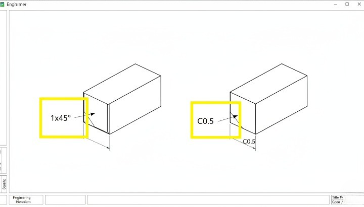
If you choose a non-45° angle, you should specify it clearly, because suppliers and inspectors will not assume it.
Functional Reasons to Use Chamfers
Chamfers solve practical production problems fast.
-
Assembly lead-in and insertion guidance A chamfer helps fasteners start smoothly. It also protects mating parts from edge damage.
-
Safety-related edge breaking A controlled chamfer reduces cut risk and handling defects.
-
Efficient deburring strategy A chamfer can replace manual deburring when you need consistent, measurable edge breaks.
When a part goes through automated assembly or high-volume handling, chamfers often reduce stoppages and cosmetic damage.
Why Chamfers Are Often Preferred in CNC Production?
Chamfers typically simplify machining and inspection.
-
Simpler toolpaths and programming Shops can cut chamfers with a chamfer mill, a spot drill, or a controlled contour pass.
-
Lower cycle time compared to fillets A chamfer pass often runs quickly, while a fillet can require more controlled contouring.
-
Easier inspection and batch consistency Inspectors can measure chamfer size and angle quickly, and operators can maintain consistency.
If you need an “edge break” more than you need stress relief, a chamfer usually gives you the most predictable result.
Fillet vs. Chamfer — Key Differences That Matter in Real CNC Projects
Fillets and chamfers differ in stress behavior, manufacturability, and inspection practicality. Engineers should not treat them as interchangeable. Instead, you should tie your edge choice to the part’s load path, assembly method, and production volume—especially when you plan CNC machining for tight-tolerance components at scale.

The fastest way to choose correctly is to compare the two options across the variables that drive cost and risk.
Stress Distribution and Structural Performance
A fillet typically improves fatigue performance because it reduces stress concentration at corners. A chamfer can reduce a sharp edge, but it usually does not spread stress as effectively under cyclic load.
You should lean toward fillets when:
-
the corner sits in a high-stress region,
-
the part sees vibration or cyclic loading,
-
failure risk matters more than machining speed.
You should lean toward chamfers when:
-
the edge mainly protects handling and assembly,
-
the corner does not sit on a fatigue-critical load path,
-
the design prioritizes cost and repeatability.
This difference often shows up in real products: brackets, mounts, and housings that crack at internal corners usually need a radius strategy, not “better deburring.”
Machinability and Cost Comparison
CNC cost follows time, tooling, and risk. Edge features drive all three.
| Factor | Fillet | Chamfer |
|---|---|---|
| Typical CNC toolpath | Contour / 3D blending | Quick 2D pass or chamfer tool |
| Internal corners | Tool radius constraint | Often easier to implement as edge break |
| Cycle time | Often higher | Often lower |
| Tool wear risk | Higher with small tools | Lower with standard chamfer tools |
| Quote variability | Higher when specs stay unclear | Lower when chamfer callout stays clear |
Engineers often overlook one cost driver: internal fillets can force smaller cutters, and smaller cutters can force slower feeds. That single chain reaction can dominate your cycle time.
Assembly, Safety, and Handling Considerations
Edge design also controls how parts behave outside the machine.
-
Manual vs. automated assembly requirements A chamfer improves lead-in. A fillet rarely acts as a clean lead-in for pins or fasteners.
-
Operator safety and ergonomics Chamfers reduce sharpness at edges that workers touch during assembly.
-
Shipping, handling, and edge damage risk Sharp edges chip and scratch. A controlled edge break reduces handling defects.
If your parts ship internationally and you see cosmetic damage claims, a consistent edge break strategy often fixes more problems than extra packaging.
Fillet vs. Chamfer from a Design-for-Manufacturability (DFM) Perspective
DFM turns “fillet vs chamfer” into a manufacturing decision: tool access, stiffness, and process control. When you align the edge design with real machining constraints, you get more stable quotes and fewer surprises during first articles.
This section usually separates “good CAD” from “production CAD.”

Internal Corners — Why Fillets Can Increase CNC Complexity?
Internal corners create the most common CNC edge trap: the cutter cannot form a perfectly sharp internal corner. When you specify a tiny internal fillet, you may force a tiny tool.
You should watch these risks:
-
Minimum tool radius rules Your internal fillet must be equal to or larger than the tool radius the shop can use.
-
Tool reach, clearance, and overcut risks Deep pockets often require long tools. Long, thin tools deflect and chatter.
-
Hidden downstream costs Small tools increase cycle time and tool wear. They also raise scrap risk during production ramp.
If you need a sharp internal corner for assembly, you can consider alternatives like relief features (for example, “dogbone” relief in some applications). However, you should tie that choice to function and inspection strategy, not to habit.
External Edges — When Chamfers Are the More Robust Choice?
External edges often favor chamfers because they support repeatable machining and consistent deburring.
-
Repeatability across production batches Shops control chamfer size easily with standard tooling and controlled tool offsets.
-
Easier deburring and finishing control A chamfer can reduce burrs at the source, which reduces manual finishing time.
When you want predictable quality at volume, a simple chamfer often beats a cosmetic fillet on external edges.
Common Over-Specification Mistakes Designers Make
Edge over-specs create quote inflation and supplier confusion.
-
Excessively small fillet radii Small radii can force small tools. Small tools raise time and risk.
-
Fillets specified where chamfers are sufficient If you only need to remove sharpness, a chamfer often meets the requirement faster.
-
Cosmetic fillets with no functional value Teams add fillets “because CAD looks better,” then they pay for slow blending toolpaths.
A practical rule helps: specify tight edge geometry only when the edge carries a clear functional role.
Fillet vs. Chamfer in Engineering Drawings and RFQs
Clear edge specifications reduce quoting noise, reduce manual finishing, and improve supplier alignment—especially when you follow a structured RFQ package such as how to prepare RFQ files for fast, accurate CNC quotes. When you leave edges vague, suppliers price risk. They also interpret “break edges” differently, which causes batch-to-batch variation.
International supply chains amplify this issue because different shops follow different defaults.
For undefined edges, ISO provides guidance through standards like ISO 13715, which addresses “edges of undefined shape” in technical product documentation. ()
How to Specify Fillets Correctly on Engineering Drawings?
You should specify fillets in a way that supports manufacturing and inspection.
-
Radius callouts and tolerance intent Call out the radius value clearly. When the radius affects function, include an appropriate tolerance strategy.
-
“Typical” fillets vs. critical features Use “TYP” only when it truly applies. Mark critical radii separately when they control stress or sealing.
-
Avoiding ambiguous or conflicting notes Do not combine “R1” callouts with vague “break all edges” notes unless you clarify priority.
If your drawing includes surface texture requirements, standards like ISO 1302 historically defined drawing symbols for surface texture indication, and newer ISO 21920 series modernizes related surface texture specification rules.
How to Specify Chamfers Clearly?
A chamfer callout should remove interpretation. You can do that with simple, standard notation.
-
Angle + size notation Use formats such as 1 × 45° or 0.5 × 45° when you want a controlled chamfer.
-
Edge break conventions and standards If you only need burr removal, you can specify a controlled “edge break” range, but you should avoid vague language.
-
When “Break all sharp edges” is acceptable — and when it is not It can work for non-critical edges on rougher industrial parts. It fails when edges control fit, sealing, cosmetic appearance, or safety-critical interfaces.
If you want a structured chamfer dimensioning approach, many GD&T education references explain common chamfer callout methods (length-by-angle, or length-by-length).
How Poor Edge Specification Inflates CNC Quotes?
Poor edge specs inflate quotes because suppliers must price uncertainty—especially when your program requires documented inspection and repeatability, which is why teams rely on quality control and inspection workflows for CNC parts.
-
Supplier risk pricing behavior When edges affect assembly or fatigue, suppliers assume worst-case effort unless you clarify intent.
-
Inconsistent interpretation across suppliers One shop hand-deburred everything. Another shop cut controlled chamfers. Quotes will not match.
-
Hidden secondary operation and inspection costs If you do not specify, suppliers may include manual finishing time as a buffer.
A simple procurement habit helps: ask suppliers to list assumptions about edge finishing in the quote. That one line often explains most quote variation.
Fillet vs. Chamfer in Different CNC Manufacturing Scenarios
Scenarios help you choose faster because they connect edge geometry to real constraints. If you know your load case, your volume, and your appearance needs, you can often pick the right edge in minutes.
High-Load Mechanical Components
High-load parts often need fillets where stress concentrates.
Common examples:
-
bearing housings with load paths around bores,
-
brackets that see vibration,
-
structural interfaces that carry cyclic loads.
In these cases, a fillet at the stress hotspot often matters more than a chamfer for handling. However, you can still use chamfers on non-critical external edges to protect assembly and reduce burrs.
High-Volume Production Parts
Volume makes time and repeatability dominate.
You should focus on:
-
cycle time sensitivity, especially for multi-edge parts,
-
stable tool life,
-
consistent deburring without hand labor.
In high volume, chamfers often win on external edges because they reduce manual finishing. When you need internal fillets, you should choose radii that match practical cutter sizes to reduce cycle time.
Precision and Cosmetic Components
Precision and cosmetic parts demand consistent edge appearance and surface behavior, especially when you specify anodizing for CNC machined aluminum parts.
You should consider:
-
visible surfaces and touch points,
-
post-processing impact (anodizing, polishing, bead blasting),
-
surface texture requirements and inspection.
For anodized aluminum, coating thickness can range from “moderate” to “hardcoat” depending on the anodizing type; references commonly describe Type II thickness in the low-micron to ~25 µm range, and Type III as thicker hardcoat above ~25 µm. (source:) That thickness can slightly change edge feel and corner definition, so you should plan your edge strategy with finishing in mind.
Fillet, Chamfer, or Bevel? Avoiding Common Terminology Confusion
Terminology errors create RFQ errors because shops build parts from words and symbols. When teams mix “bevel,” “chamfer,” and “fillet,” they often create rework loops during first article review.
You can avoid this with a simple rule: name the geometry you want, then dimension it clearly.
Fillet vs. Chamfer vs. Bevel — Clear Definitions
-
Fillet A rounded transition defined by a radius (R).
-
Chamfer A beveled edge, often defined by size × angle (commonly 45°).
-
Bevel A broader term that can mean an angled edge, often used in welding prep or general machining language.
Typical use cases in CNC machining:
-
You use fillets to manage stress and create smooth internal transitions.
-
You use chamfers to break edges and guide assembly.
-
You use bevel language when the industry context expects it, but you still dimension the edge precisely.
Why Misused Terms Cause RFQ and Production Issues?
Misused terms create misalignment between CAD intent and shop-floor execution.
-
CAD intent vs. shop-floor interpretation CAD models may show a rounded edge, but the drawing may call for a chamfer—or vice versa.
-
International supplier communication risks Different regions and shops treat “edge break” language differently. You reduce risk when you specify measurable geometry.
If your team uses general tolerances for unspecified dimensions, standards such as ISO 2768 help teams define default tolerances and reduce drawing clutter. That approach can help, but you should still treat functional edges as controlled features.
How to Choose Between Fillet and Chamfer — A Practical Decision Guide?
You can choose the right edge feature when you connect edge geometry to function and process. If you want a shortcut, start with the question: “Does this corner control stress life, or does it mainly control handling and assembly?”
Then apply the decision rules below.
Choose a Fillet When:
-
Fatigue or stress concentration is critical Use a fillet when the corner sits on a load path and sees cyclic stress.
-
Structural continuity affects part performance Use a fillet when a sharp transition would create cracking risk or stiffness discontinuity.
Practical design tip: pick internal radii that support realistic cutter sizes and access. That choice often cuts cycle time without changing function.
Choose a Chamfer When:
-
Assembly speed and robustness matter Use a chamfer when you need a lead-in for mating parts or fasteners.
-
Cost and machining simplicity are priorities Use a chamfer when you want consistent edge breaks with minimal toolpath complexity.
-
Edge breaking is the primary requirement Use a chamfer when you mainly want burr control, safety, and handling protection.
If you want a controlled “edge break” without over-specifying every edge, you can combine local chamfer callouts on critical edges with a general ISO-style undefined edge approach (for example, ISO 13715) for non-critical edges. (source:)
When to Involve Your CNC Supplier for DFM Input?
You get the best ROI from supplier DFM input when you act early.
-
Early design stages You can adjust radii and chamfers before they lock into fixtures and inspection plans.
-
Cost-down or redesign efforts You can often remove cosmetic fillets, standardize chamfers, and reduce tool changes.
-
Transition from prototype to mass production You can redesign internal corners to match production tooling and stabilize quality.
A capable supplier will not just “quote the drawing.” They will highlight which edge specs drive cycle time and which ones protect function.
Conclusion
Fillet vs chamfer is a functional engineering choice, not a styling preference. When you align edge geometry with load paths, assembly needs, and CNC realities, you reduce cost, shorten lead time, and improve quality consistency.
If you want more stable quotes and fewer first-article surprises, start with one habit: make edge intent measurable on the drawing and explicit in the RFQ.
If you want HM to review your edge specs during DFM—especially for internal corners, deburring strategy, and finish impact—you can request a DFM review and quote.