
Cantilever Snap Joint Design: Formulas & Materials
Snap fits look simple, but production failures are predictable: root cracking or whitening, assembly force variation, and retention loss from creep.
Many teams also learn the hard way that the “same” snap geometry can work in a CNC prototype yet fail after switching to injection molding. Draft, shrink and warp, knit lines, and surface finish can shift the real interference and weaken the root.
This guide gives you a practical cantilever snap joint and snap fit framework for CNC machining and injection molding. You will define the key inputs, size the snap beam with simple formulas, and lock reliability with manufacturability rules.
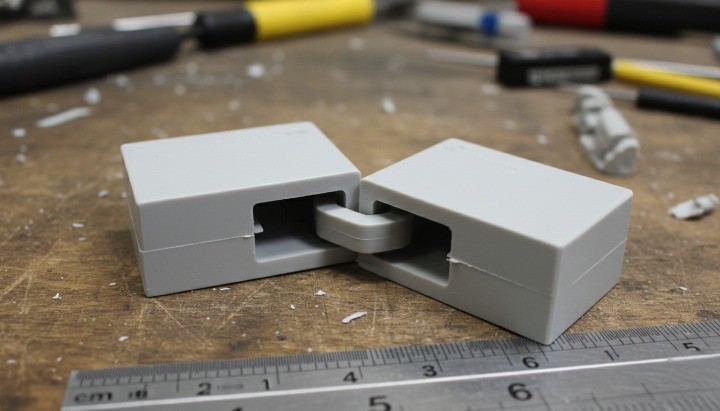
When to use cantilever snaps?
Good fit when:
-
You want tool-less press assembly (and simple service release)
-
The joint can tolerate some dimensional variation
-
You can make the beam long enough to flex safely
-
Retention requirement is moderate (not a structural latch)
Avoid when:
-
Safety-critical high retention loads are required
-
The snap must hold high constant stress for years (creep risk)
-
High heat/chemicals/UV reduce toughness
-
The root geometry is hard to control (sharp corners, thin sections, knit lines)
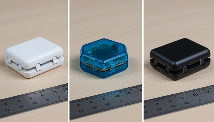
Snap fit deflection force cycles
Before material selection or tooling quotes, define:
-
Required deflection (Y) at the snap tip to clear the undercut
-
Acceptable assembly force (hand push vs fixture press)
-
Expected cycles (one-time vs repeated opening/closing)
If these aren’t defined, the snap is easy to “almost work” and hard to stabilize.
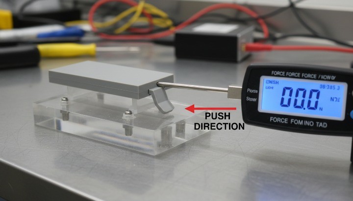
CNC vs injection molding
Mass production: design for injection molding first draft, uniform walls, undercut strategy, creep and fatigue.
Prototype or low volume: CNC can be fast, but you must design for tool access, inside radii, and burr control. For fast iterations before tooling, use small batch CNC machining for snap fit prototypes.
Fast sizing rules
Use these as first-pass sanity checks. They don’t replace testing, but they prevent the most common geometry mistakes.
-
L/t ratio (beam length / thickness): aim ~8–12 for typical snaps; if you’re below ~6, cracking/force spikes become likely.
-
Undercut: keep it “as small as function allows”; large undercuts force large deflection and high root strain.
-
Root fillet: use the largest feasible radius and avoid abrupt thickness steps at the root.
-
Stop feature: treat a hard stop as “standard,” not optional, when hand assembly variation exists.
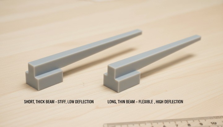
Cantilever snap geometry basics
A cantilever snap is a system: beam, hook, and surrounding support. When the hook ramp, reliefs, and fillet transitions are critical, CNC milling components for snap features can help you control the geometry and edge quality during iterations.
Snap beam thickness
The beam is your spring.
-
Increasing length (L) makes the snap more compliant (lower force for the same deflection).
-
Increasing thickness (t) makes it dramatically stiffer and raises root strain quickly.
-
Increasing width (b) increases stiffness too, but thickness is the most sensitive lever.
Practical rule: if the snap cracks, first ask whether the beam is too short or too thick for the required deflection—not whether the material is “strong enough.”

The hook: lead-in ramp, undercut, retention face
Hook geometry controls how smoothly the snap assembles and how much retention you get:
-
A smoother lead-in ramp lowers peak insertion force but increases travel.
-
The undercut drives required deflection and stress.
-
The retention face angle determines whether load tends to release the snap or lock it in place.
Think of the hook as a cam: it converts assembly motion into beam deflection—and it can create force spikes if the ramp is steep or friction is high.
Where most snaps fail?

Most snap failures start at the beam root.
-
Use a generous root fillet (as large as the design allows).
-
Avoid sudden thickness transitions at the root.
-
If you need more support, add local backing/ribs in the base instead of making the beam thicker.
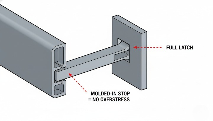
Stop features for reliability
Many snaps fail from over-travel (the assembler pushes past what’s needed to clear the undercut). Add a hard stop so once latched, additional force transfers into a stop—not more beam strain.
Quick troubleshooting
Use this when something “almost works” but isn’t stable.
-
Root crack / whitening at first assembly → Beam too short/thick, sharp root, steep ramp, or no stop. Fix: increase L, reduce t, enlarge root fillet, smooth ramp, add stop.
-
Insertion force varies a lot lot-to-lot → Interference window too tight, friction/finish inconsistent, burrs. Fix: widen tolerance window, control surface finish/deburr, reduce undercut, add lead-in.
-
Retention drops after weeks/months → Constant deflection in service (creep), temperature too high for resin grade. Fix: redesign so snap relaxes after latch, reduce long-term strain, add secondary retention, validate at temperature.
-
Works in CNC prototype but fails in molded parts → Draft/shrink/warp/knit line changed interference and root strength. Fix: design for molding rules first, validate undercut strategy early, test molded samples for creep/fatigue.
-
Hard to machine / expensive setups → Hidden undercuts, tiny radii forcing micro tools, unstable thin beams. Fix: re-orient undercut for tool access, add reliefs, standardize radii, adjust machining sequence/support.
Snap fit design calculations
Use these equations to size the snap and compare concepts early. To make the results manufacturable and inspectable, define your critical snap dimensions and datums clearly in the drawing—see GD&T basics for snap fit tolerances.
Variables
-
L= beam length (root to load point) -
b= beam width -
t= beam thickness (in bending direction) -
E= Young’s modulus -
F= load near the tip -
δ= tip deflection under load
Second moment of area (rectangular section)
I = b * t^3 / 12
Thickness is cubed—small changes in t have huge effects.
Tip deflection and force
For a cantilever with a tip load:
δ = F * L^3 / (3 * E * I)
Rearranged to estimate force for a target deflection:
F = 3 * E * I * δ / L^3
Root bending stress (screening metric)
Max bending moment at the root: M = F * L Peak bending stress (ignoring stress concentration):
σ_max = 6 * F * L / (b * t^2)
From undercut to required deflection (include tolerance stack)
Required deflection is not just the nominal undercut. Include:
-
Mold shrink/warp variation (molding)
-
Machining tolerances + burrs (CNC)
-
Assembly misalignment/approach angle
To make this work in production, define a tolerance window that matches your process capability—see CNC machining tolerance for interference fits.
Using the formulas correctly
These equations are best for early sizing. Move to FEA + physical testing when:
-
Deflection is large relative to thickness (nonlinear bending)
-
You need repeated cycling (fatigue) or long-term retention (creep)
-
Root region has knit lines, sharp transitions, or complex curvature
-
The snap is high-value, safety-critical, or must work across temperature/humidity
Principle: formulas set the size range; FEA+testing set the reliability boundary.
Material tips for plastic snap joints
Snap material choice is a balance of stiffness, ductility, fatigue resistance, and creep behavior.
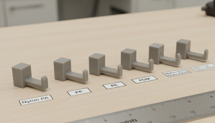
Nylon (PA): strength/fatigue vs moisture sensitivity
Nylon is common for snaps because it can combine good strength and toughness.
-
Moisture absorption can change stiffness and dimensions
-
“Dry-as-molded” and “conditioned” behavior can differ
Choose Nylon when:
-
You need higher retention with manageable beam sizes
-
You expect repeated cycling
-
You can define/accept conditioning assumptions
Watch out when:
-
Tight dimensions must hold across large humidity swings
Polypropylene (PP): ductility vs creep tradeoffs
PP is valued for ductility and flexible snap behavior.
-
Low stiffness often requires larger sections for the same feel/retention
-
Creep can reduce retention when the snap holds constant deflection
Choose PP when:
-
You want easier assembly and lower peak stress
-
Chemical resistance and cost matter
-
The design relaxes after assembly (low long-term strain)
Watch out when:
-
You need high retention in small geometry
-
The snap must hold constant strain for years
Acetal (POM), ABS, PC: quick guidance
-
POM: low friction and good dimensional stability for clips/sliding interfaces
-
ABS: good toughness; snap performance depends heavily on geometry and environment
-
PC: tough and stiff but notch-sensitive; root fillet quality matters
Environment is the real material test
-
Heat accelerates creep and lowers stiffness
-
Chemicals can reduce toughness or trigger stress cracking
-
UV can embrittle unstabilized grades
If retention must hold for years, validate at real exposure conditions—not just room-temperature datasheets.
Injection molding vs CNC snap fits

Molded snaps: draft, wall thickness, knit lines, ejection
-
Add draft on beam and hook sidewalls for clean ejection
-
Keep wall thickness transitions smooth to reduce sink/warp
-
Avoid knit lines at the root (gate strategy matters)
-
Plan ejection so pins don’t distort or mark the snap feature
If your snap requires zero draft and razor edges, you’re designing for CNC—not molding.
Undercuts in molding: slides/lifters vs bump-off release
Undercuts drive tooling cost:
-
Slides/lifters: robust and repeatable but add complexity and cost
-
Elastic bump-off: depends heavily on resin ductility, draft, and undercut geometry
If you plan bump-off, validate feasibility early with the molder.
CNC snaps: tool access, inside radii, burr control
-
Inside corners will be radiused—design fillets intentionally
-
True undercuts may need side access, extra setups, or 4/5-axis work
-
Thin beams can vibrate; plan machining strategy and support
-
Burrs/edge quality change insertion force—define deburr rules on hook edges
A robust path from prototype to production
-
Use CNC/3DP to validate fit, motion, and insertion force feel
-
Update geometry based on real assembly behavior (ramp, undercut, stop)
-
Mold samples to validate creep/fatigue and production variation (shrink/warp, knit lines)
Undercut machining for snaps
Design to avoid hidden undercuts
-
Orient the snap so the undercut opens toward a reachable tool direction
-
Avoid reverse undercuts that require special tooling or setups
-
Consider splitting a feature into two parts if it removes an undercut
Add reliefs to make toolpaths possible
-
Add clearance behind the retention face for tool cleanup
-
Avoid tiny internal radii that force fragile micro tools
-
If a sharp edge is functional, isolate it with nearby relief
Inspection plan for interference and retention features
Plan inspection for:
-
Undercut depth (effective interference)
-
Beam thickness at the root
-
Root fillet presence/quality
DFM geometry material process
Freeze the design only after reviewing these high-failure patterns.
| Design choice | Why it matters | Injection molding notes | CNC notes | Material notes (Nylon/PP) | Risk-reducing fix |
|---|---|---|---|---|---|
| Short, thick beam | High root strain for required deflection | Warp + knit line risk at root | Vibration risk; thickness variation changes force | PP may creep; Nylon still notch-sensitive | Increase L, reduce t, add stop |
| Sharp root corner | Stress concentration → cracking | Fill + knit lines amplify weakness | Tool marks can act as notches | Both benefit from generous fillets | Add root fillet; smooth transition |
| Large undercut depth | Drives deflection and force | May require slides/lifters or bump-off validation | May require side milling / extra setups | PP flexes but may creep; Nylon stronger but humidity-sensitive | Reduce undercut; optimize ramp; add stop |
| Steep lead-in ramp | Force spikes / whitening | Draft and surface affect friction | Burrs/finish change friction | Additives affect friction | Smoother ramp; control surface; test early |
| Constant high deflection in service | Creep reduces retention | Resin + temperature dominate | Same creep risk | PP often more creep-sensitive | Redesign so snap relaxes after latch; add secondary retention |
| Tight tolerance on interference | Intermittent failures | Shrink/warp variation is real | Burrs + tolerances add variation | Nylon moisture shifts dimension | Add compliance; widen window; design worst-case |
If you change only one thing, prioritize: root fillet + stop feature + tolerance window.
RFQ checklist for quotes
RFQ inputs that prevent quote swings and late redesign
On the drawing, call out these CTQs:
-
Material callout (grade if known) + conditioning assumption (especially Nylon)
-
Undercut/interference (nominal + tolerance)
-
Beam thickness at the root + minimum root fillet radius
-
Surface finish/deburr where friction affects feel/force
For first articles, ask for evidence, not just dimensions:
-
Measured undercut/interference + root thickness
-
Assembly observations: insertion feel, whitening, crack signs
-
For molded parts: gate/knit line notes near the snap root
Conclusion
A good cantilever snap joint is not “a hook that clicks.” It’s a controlled elastic system. Do three things well—size L/t correctly, protect the root, and prevent over-travel—and you will reduce cracking, reduce insertion-force variation, and improve production consistency.
If you’re building a snap-fit assembly and want a quick risk review, share your CAD files for a fast snap-fit RFQ. Include your target material (Nylon/PP or other), environment, and expected cycles. We can suggest a manufacturable snap geometry and quote CNC prototypes or injection molding options.
FAQ
How do I calculate snap fit force and stress?
Use a simplified cantilever model:
-
δ = F * L^3 / (3 * E * I) -
F = 3 * E * I * δ / L^3 -
σ_max = 6 * F * L / (b * t^2)Then validate with FEA + testing for plastics, large deflection, creep, or fatigue.
Why do snap fits crack or whiten at the root?
Because root bending moment is highest, and sharp corners/defects amplify stress. A generous fillet plus a stop feature are common fixes.
Is Nylon or PP better for snap joints?
-
Nylon: stronger/stiffer and often better fatigue, but moisture affects stiffness and dimensions.
-
PP: more ductile and assembly-friendly, but creep can reduce long-term retention. Choose based on cycles, environment, and whether the snap holds constant strain.
Can I CNC machine snap fits intended for molding?
Yes, but don’t assume 1:1 transfer. Molding needs draft, and shrink/warp changes interference. Use CNC to validate fit and feel, then validate with molded samples for creep and repeatability.
How do I handle undercuts in injection molding?
Usually slides/lifters (robust but costly) or elastic bump-off (material/geometry dependent). Decide early—undercut strategy often drives tool cost and lead time.