
CNC Threading Methods: Tapped Holes vs Thread Milling vs Thread Insert
This guide explains key CNC threading methods for internal threads.
If you design or source machined and die-cast parts, you already know that a single failed thread can stop an entire assembly, delay a launch, or trigger expensive rework. Threaded features carry load, seal fluids, and hold critical components together, so thread quality directly affects reliability, warranty risk, and safety.
Yet many teams still choose tapping, thread milling, or thread inserts by habit rather than by clear criteria. In this article, you will see how each method works, where it wins, where it fails, and how you can make better decisions and work more effectively with your CNC machining supplier.
Overview of CNC Threading Methods
In CNC machining, engineers use several different methods to create internal threads because no single process works best for every material, geometry, and production volume. Tapped holes, thread milling, and thread inserts each balance speed, cost, flexibility, and strength in different ways, and understanding these trade-offs is the first step toward reliable threaded parts.
At a high level, tapping creates threads in one fast operation with a dedicated tool, thread milling uses a cutting tool that follows a helical path to form the profile, and thread inserts add a separate threaded element into a prepared hole. You can combine these methods within the same project, especially when you machine or finish aluminum and zinc die-cast components and need both productivity and robustness.
Why Multiple Threading Methods Exist in CNC Machining?
CNC shops use multiple threading methods because real-world projects rarely share the same constraints. You might have a small batch of prototypes in stainless steel, a high-volume aluminum housing with many shallow blind holes, and a safety-critical joint that must survive thousands of assembly cycles across CNC machined parts with threaded features. Each scenario pushes you toward a different balance of risk, cost, and precision.
Tapping offers very fast cycle times for common thread sizes, but it can struggle with difficult materials or deep blind holes. Thread milling is slower per hole but gives you excellent control, especially in hard or high-value parts. Thread inserts add extra assembly steps, yet they provide strong and repairable threads in soft substrates. When you understand why these options exist, you can start to select them intentionally instead of treating threading as a simple afterthought.
What Are Tapped Holes?
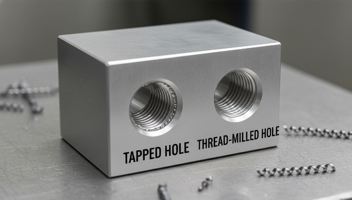
Tapped holes are internal threads produced with a tap, a tool that has the same basic profile as the finished thread. In CNC machining, the machine synchronizes spindle rotation and feed to drive the tap into a drilled hole and reverse it out, forming the thread in a single, rapid operation. This makes tapping the default choice for many standard threaded features in steel and aluminum parts.
You can use different tap types—spiral point, spiral flute, forming taps—depending on whether the hole is through or blind and how chips need to leave the cutting zone. Modern CNC machines often support rigid tapping, which improves accuracy and tool life compared with older floating holders. However, tapping remains relatively unforgiving: if the tap breaks, you usually scrap the part or spend significant time removing the broken tool from the hole.
What Is Thread Milling?
Thread milling uses a rotating cutting tool, usually with a partial thread profile, that moves along a helical path to generate the internal thread. Instead of driving a tap straight in and out, the CNC machine interpolates circular motion in X–Y while advancing in Z, so you cut the thread form gradually. This method gives you excellent control over diameter, depth, and even left- or right-hand direction using the same tool family.
Because thread milling does not lock a tool in the hole, the risk of catastrophic breakage is lower, especially in hard or tough materials. You can also fine-tune the thread size by adjusting the milling path, which helps when you chase tight tolerances or compensate for plating and coatings. The trade-off is longer cycle time and a higher need for good CAM programming and machine rigidity, which is why many shops reserve thread milling for critical features, large diameters, or difficult materials instead of every hole.
What Are Thread Inserts? (Helicoil, Keensert, Wire Inserts, Solid Inserts)
Thread inserts are separate threaded elements that you install into a prepared hole to create the final internal thread. Common types include wire inserts such as Helicoil, key-locking inserts such as Keensert, and various solid bush-style inserts. In all cases, you first machine a specific pilot hole and often a special thread, then install the insert to provide a durable, wear-resistant, and often stronger thread than the base material itself.
Wire inserts use a coiled wire with a diamond cross-section to form the internal thread, which is especially helpful in soft alloys like aluminum and magnesium. Solid and key-locking inserts provide even more robustness, with mechanical keys or shoulders that resist rotation and pull-out in high-load applications. These solutions add cost and assembly time, but they allow repeated assembly, field repair, and high clamp loads in materials that would otherwise strip easily. As a result, thread inserts play a critical role in aerospace, automotive, and machinery components that combine light alloys with demanding mechanical requirements.

Tapped Holes
How CNC Tapping Works?
CNC tapping creates internal threads by driving a tap into a pre-drilled hole while the machine synchronizes spindle rotation and feed. The tool cuts or forms the thread profile as it advances and then reverses out of the hole along the same path. You get a complete thread in one continuous, fixed cycle.
In production, the process usually looks like this: you drill to the correct tap drill size, deburr or chamfer the hole mouth, and then run a rigid tapping cycle or use a floating tap holder. The CNC program controls depth, speed, and feed according to thread size and material. Coolant and chip evacuation are critical, especially in blind holes. This workflow depends on accurate CNC drilling of tap-ready holes, which ensures the right pilot diameter and alignment before tapping begins.
For buyers and engineers, the key point is simple: tapping is a fast, standardized way to produce a lot of internal threads at low cost, as long as the design and process conditions are reasonable.

Advantages (Speed, Cost Efficiency, Mature Process)
Tapping remains the default choice for many internal threads because it is fast, predictable, and widely understood across shops worldwide. When you look at cycle time and cost per hole, tapping is often the most economical option, especially for small and medium thread sizes.
Main advantages include:
-
High productivity One tap cycle completes the full thread in a single pass. For commonly used sizes such as M4–M10 or 8–32 to 3/8″-16, cycle times are very short. This matters when your part has dozens of holes.
-
Low cost per thread Taps are relatively inexpensive and widely available. Programming is simple. On a stable process, you can spread the cost over thousands of holes with consistent output.
-
Mature, standardized process Standards such as ISO metric threads and Unified thread series define geometry, classes of fit, and tolerances, so engineers can rely on established rules rather than guesswork. This also makes it easier to inspect threads with go/no-go gauges and thread plugs.
-
Wide compatibility with CNC machines Most modern machining centers support rigid tapping cycles. Even older machines can tap with suitable holders, which means you do not need special hardware in many cases.
From a sourcing and cost perspective, tapping is often the best starting point when you have standard thread sizes, moderate strength requirements, and medium-volume production.
Limitations (Tool Breakage, Chip Evacuation, Material Challenges)
The same characteristics that make tapping fast and economical also create risk. A tap is a slender, relatively fragile tool. If something goes wrong, it can break deep inside the hole, and removal can be difficult or impossible without scrapping the part.
Typical limitations include:
-
Tool breakage risk A tap engages multiple teeth at once. If chips pack in the flutes, lubrication is poor, or the feed is incorrect, the tool can jam. In blind holes and hard or sticky materials, the risk increases. A broken tap in an expensive part can wipe out the cost advantages of tapping.
-
Chip evacuation in blind holes In materials like stainless steel or low-carbon steel, long stringy chips can clog the flutes. In blind holes, chips have nowhere to go unless you manage them with spiral flute taps, high-pressure coolant, or peck cycles. Poor chip control leads to rough threads and tool failure.
-
Limited flexibility for non-standard threads Each thread size and pitch needs its own tap. If you work with many special or large thread sizes, your tooling inventory grows and setup becomes more complex.
-
Sensitivity to hole size and alignment If the tap drill is too small, torque spikes and the tap can break. If the drill wanders and the hole is not aligned, the tap will try to follow a bad path and damage the thread.
-
Challenging materials Hard steels, high-temperature alloys, or abrasive materials reduce tap life and increase breakage risk. Form tapping in ductile materials helps in some cases, but you still need very tight process control.
When you design parts with many tapped holes in difficult materials, you should actively weigh these risks against alternatives such as thread milling or inserts, especially for high-value components.
Typical Failure Modes
Understanding how tapped threads fail helps you design for reliability and choose the right process window. Most issues fall into a few repeatable patterns that you can anticipate before production.
Common failure modes include:
-
Broken taps in the hole This is the most serious failure. It often comes from excessive torque, wrong drill size, poor lubrication, or incorrect feed/speed. Removal may require EDM or manual rework, and many parts end up scrapped.
-
Oversized or undersized threads If the tap drill is wrong or wear is not monitored, threads may be too tight or too loose. This leads to assembly issues, cross-threading, or reduced load capacity.
-
Poor surface finish and burrs Worn taps, low cutting speeds, or insufficient coolant cause rough flanks, torn material, and heavy burrs at the hole entrance or exit. Burrs can interfere with seals or moving parts and often require extra deburring.
-
Misaligned or tilted threads Misalignment between the drilled hole and the tap axis produces threads that are not perpendicular to the surface. Fasteners may bind, or assemblies may not seat correctly, especially on sealing faces.
-
Thread stripping in soft materials In aluminum, zinc alloys, or plastics, coarse threads cut by taps can strip under high load or repeated assembly. This is a design issue more than a cutting issue, but it shows the limits of direct tapping in soft materials.
These failure modes highlight an important point: tapping itself is not “bad,” but it has a narrow comfort zone. Once you push beyond that zone in terms of depth, material, or load, you should consider other methods.
Best Use Cases and Suitable Materials
Tapped holes work very well when you match the method to the right application. As a rule of thumb, you get the best results when the material, thread size, and production volume sit in the “sweet spot” for tapping.
Good use cases include:
-
Standard small to medium threads Sizes like M3–M12 or #4–1/2″ in mild steel, free-machining steel, aluminum, and brass are ideal. You can achieve high throughput and stable tool life in CNC steel parts with tapped threads.
-
Through holes or shallow blind holes Through holes naturally help chip evacuation. Shallow blind holes with proper chamfer and drill depth also work well, as long as you avoid chip packing at the bottom.
-
Medium production volumes If you run batches from hundreds to low tens of thousands of parts, tapping offers a strong balance of tool cost, speed, and simplicity.
-
Components with moderate thread strength requirements Structural brackets, housings, covers, and general mechanical parts often fall in this category. Threads see normal assembly loads, not extreme fatigue or abusive service.
Suitable materials typically include:
-
Aluminum alloys with good machinability
-
Free-machining carbon steels
-
Many stainless steels when you choose appropriate tap geometry and coolant
-
Brass and copper alloys for precision threads
In contrast, very hard alloys, highly abrasive materials, and very soft plastics often need a different approach such as thread milling or inserts.
Summary — When Tapping Is the Best Choice?
Tapping is still the most efficient internal threading method in many CNC machining scenarios, but only when the conditions are right. You get maximum benefit when you:
-
Use standard thread sizes in machinable metals.
-
Design through holes or manageable blind holes with proper drill depth and chamfer.
-
Aim for medium production volumes where cycle time dominates cost.
-
Accept that thread strength and flexibility are adequate with direct tapped threads.
If your part fits this profile, CNC tapping should usually be your first choice, and you can keep costs under control with sensible tool management and process monitoring. However, when you face deep blind holes, difficult materials, critical load-bearing threads, or expensive parts where scrap is unacceptable, you should seriously evaluate thread milling or thread inserts as more robust alternatives.
Thread Milling
How Thread Milling Works? (Helical Interpolation Basics)
Thread milling creates internal threads by using a rotating cutting tool that traces a helical path inside a pre-drilled hole. Unlike tapping, where the tool matches the thread profile, a thread mill usually carries only part of the profile and machines the thread by moving in coordinated X-Y-Z axes. The CNC machine controls this motion precisely, so you form the thread progressively rather than in a single pass.
In practice, the operator drills the correct pilot hole, programs the helical interpolation cycle, and chooses a multi-flute or single-point thread mill depending on size and precision. The tool moves in a circular pattern while advancing in Z at a rate equal to the thread pitch. Because nothing locks the cutter in the hole, you avoid the torque spikes that cause tap breakage. You can also adjust the toolpath to compensate for tool wear, coatings, or tight tolerance requirements.
Thread milling is especially valuable when you need high precision, large diameters, or improved reliability in expensive or difficult-to-machine materials.

Advantages (Flexibility, Accuracy, Large Threads, Hard Materials)
Thread milling offers significant advantages when you look beyond cycle time and consider precision, control, and risk. It solves many of the problems inherent in tapping by reducing cutting forces and giving the programmer control over thread geometry.
Key advantages include:
-
High flexibility across many thread sizes One thread mill can produce different diameters and left- or right-hand threads by changing the toolpath, not the tool. This reduces tooling cost when you work with many sizes or non-standard pitches.
-
Greater accuracy and adjustability You can fine-tune the thread’s pitch diameter by adjusting the cutter’s radial offset. This is extremely useful when holding close fits such as 6H / 6g tolerance classes or UNJ / UNF profiles that require precise control.
-
Excellent performance in hard or tough materials Because only one or a few cutting edges engage at a time, thread milling reduces torque and improves chip evacuation. It is common in stainless steels, titanium, and high-temperature alloys, where tapping is risky.
-
Safe operation with lower breakage risk The tool never becomes trapped in the hole. If something goes wrong, the tool retracts without catastrophic failure. This reduces scrap on expensive components.
-
Superior control for blind holes You can control thread depth precisely without bottoming out or forcing chips into the hole base.
For buyers, the main advantage is simple: thread milling reduces risk on difficult parts, improves dimensional control, and supports specialized threads without costly tooling changes.

Limitations (Slower Cycle Times, Higher Programming Skill)
Thread milling is powerful, but it is not always the right choice. The process requires more machine time and programming effort compared with tapping. It also depends on machinery stiffness and CAM support.
Common limitations include:
-
Slower cycle times than tapping Tapping creates threads in one quick stroke. Thread milling requires a full helical toolpath and may use multiple passes for accuracy. On parts with many holes, the time difference adds up.
-
Higher programming complexity The programmer must generate a helical interpolation cycle and tune feed, speed, and cutter offset. Inexperienced teams may overcut or undercut the thread if the toolpath is incorrect.
-
More sensitive to machine rigidity and runout Thread milling requires accurate circular interpolation. Machines with worn guideways, poor rigidity, or excessive spindle runout may struggle to maintain pitch diameter and thread form.
-
Tool cost can be higher Thread mills cost more per piece than basic taps, especially for large pitches or coated tools designed for exotic materials. However, their longer life and lower breakage risk often offset that cost in critical applications.
-
Limited benefit for simple, high-volume parts If you have thousands of standard M6 or M8 threads in aluminum housings, tapping is much more efficient and cost-effective.
These limitations highlight a clear rule: thread milling is ideal for precision or high-risk threads, not for fast throughput on standard features.

Typical Failure Modes
While thread milling reduces catastrophic failures, it still presents several repeatable issues that engineers need to consider. Understanding these modes lets you design better features and write more reliable specifications.
Typical failure modes include:
-
Incorrect pitch diameter due to incorrect toolpath offset A small error in radial offset shifts the pitch diameter, leading to loose or tight fits. This problem is usually process-related rather than tool-related.
-
Poor thread finish from incorrect feed or worn tools Too slow a feed or a worn cutting edge produces tearing or rough flanks. This affects tightening torque, sealing, and thread life.
-
Tool deflection in deep or narrow holes Long-reach thread mills can deflect, producing taper or inconsistent depth, especially in parts with high aspect ratio holes.
-
Overcutting from incorrect Z-axis synchronization If the pitch feed in Z does not perfectly match the programmed pitch, the resulting thread form may be distorted.
-
Chatter or vibration in hard materials Thread milling stainless steel or titanium sometimes introduces vibration marks if the tool or holder lacks rigidity.
Compared with tapping failures, these issues rarely destroy the part. They usually show up as tolerance or finish concerns, which you can correct through process tuning.

Best Use Cases and Suitable Materials
Thread milling excels when you value accuracy, durability, and reduced risk more than pure speed. It is also the preferred option when threads interact with functional surfaces such as sealing faces or precision assemblies.
Best use cases include:
-
Large-diameter internal threads Sizes above M12 or 1/2″ benefit from thread milling due to torque reduction and flexibility.
-
Hard or exotic materials Titanium, Inconel, hardened steels, and other alloys respond better to the lighter cutting forces of thread milling.
-
Critical engineering threads Threads involved in load-bearing joints, torque-controlled assemblies, sealing surfaces, or repeated disassembly cycles should favor thread milling.
-
Low to medium production volumes When cycle time is not the dominant cost factor, thread milling offers better reliability and reduced scrap.
-
Threads in expensive or complex parts When part value is high, even one broken tap can ruin the economics. Thread milling protects project cost and delivery schedules.
Suitable materials include:
-
Stainless steels such as 304, 316, 17-4PH
-
Titanium or aerospace alloys
-
Hardened steels up to moderate hardness levels
-
Aluminum or magnesium when high accuracy is required
-
Zinc die-cast parts that require post-machined precision threads

Summary — When Thread Milling Is the Best Choice
Thread milling is the right choice when you need accuracy, predictability, and control, especially in challenging materials or high-value parts. You benefit most when:
-
The thread is large, deep, or located near a critical surface.
-
You work with hard, tough, or abrasive materials.
-
Scrap from tool breakage would be expensive or unacceptable.
-
You require tolerance tuning, compensation for coatings, or specialized thread forms.
-
Production volumes do not justify tapping’s speed advantage.
When these conditions apply, thread milling provides a durable, precise, and repeatable solution that reduces project risk and improves long-term reliability. It is often the best method for demanding industrial applications where consistency matters more than cycle time.
Thread Inserts
Types of Thread Inserts (Wire, Solid, Key-Locking)
Thread inserts create durable internal threads by placing a hardened or reinforced threaded element inside a prepared hole. Engineers use them when the base material cannot support repeated tightening cycles or high clamp loads. The three most common types—wire inserts, solid inserts, and key-locking inserts—serve different technical requirements.
Wire inserts such as Helicoil use a stainless-steel coil with a diamond cross-section. Once installed, the coil expands slightly to hold itself in place and provide a hard, smooth thread form. Solid inserts resemble small threaded bushings and offer a thicker wall for higher strength or better heat resistance, including options such as precision brass threaded inserts that provide enhanced wear resistance and dimensional stability. Key-locking inserts include mechanical keys that lock the insert into the parent material, which prevents rotation or pull-out in applications with heavy vibration or frequent disassembly.
Each type requires a specific installation sequence, normally involving drilling, tapping with a special insert tap, and then inserting the wire or bushing. Most inserts conform to established thread standards such as ISO 68-1 or Unified Screw Thread Standards, making them compatible with standard fasteners.

Advantages (Strength, Wear Resistance, Repairability)
Thread inserts offer important advantages when the application demands strength, durability, or frequent service. Their primary benefit is the ability to create threads that outperform the surrounding material, especially in lightweight alloys.
Key advantages include:
-
High pull-out strength and load capacity The insert’s hardened steel or alloy structure carries more load than the softer aluminum or magnesium around it. This improves joint reliability in assemblies with torque-critical fasteners.
-
Superior wear resistance Steel-on-steel thread interfaces resist galling, corrosion, and thread erosion. This reduces long-term degradation when components are assembled and disassembled many times.
-
Repairable and replaceable If a threaded hole becomes damaged, you can remove and replace the insert without scrapping the part. This lowers maintenance costs in machinery, engines, and aerospace equipment.
-
Stable thread geometry under temperature changes Inserts help maintain dimensional stability, which supports sealing performance in applications exposed to temperature cycling.
-
Useful for restoring stripped or oversized holes Maintenance teams often use inserts to salvage valuable components that would otherwise be discarded.
For parts where joint integrity is mission-critical, inserts provide a level of durability that direct tapping cannot match.
Limitations (Cost, Additional Assembly Step)
Despite their benefits, thread inserts introduce complexity and cost that do not suit every project. These constraints help determine when inserts are practical and when they are excessive.
Common limitations include:
-
Higher part cost Inserts add material and labor, especially when a large number of threads require reinforcement. Solid or key-locking inserts cost more than wire inserts, and installation effort varies by type.
-
Extra machining and installation steps Each insert needs a precisely sized hole and a special thread profile created by an insert tap. After machining, the operator installs the insert with a dedicated tool. This increases cycle time and part handling.
-
Potential for assembly errors Incorrect installation depth, crooked insertion, or missing locking keys can compromise thread performance. Quality checks are essential to avoid these issues.
-
Limited benefit in strong base materials In medium- to high-strength steels, inserts often provide little or no advantage compared with direct tapping or thread milling.
-
Space constraints in thin-walled parts Inserts require wall thickness that some designs cannot support without risking deformation.
These limitations mean you should apply inserts selectively in applications where durability, repairability, or load capacity clearly justify the added cost.
Typical Failure Modes (Insert Pull-Out, Cross-Threading)
Thread inserts provide strong threads when installed correctly, but they still fail under specific conditions. Understanding these failure modes helps engineers improve hole design, specify proper insert types, and avoid downstream assembly issues.
Typical failure modes include:
-
Insert pull-out under tensile load This happens when the parent material is too thin or too weak to support the insert’s outer threads. It also occurs when the hole is not drilled to the correct depth or diameter.
-
Rotation within the parent material Wire inserts can rotate if the internal driving tang is not fully removed or if the hole is oversized. Key-locking inserts reduce this risk, but improper key engagement may allow rotation.
-
Cross-threading during bolt installation Misalignment or worn bolts can damage the internal form of the insert, especially in applications with poor assembly practices or limited visibility.
-
Thread wear from abrasive environments Although inserts are robust, contaminants such as metal debris or abrasive particles accelerate wear.
-
Back-out during vibration Inserts may gradually work loose if the application lacks locking features or if the insert’s outer threads were not installed with proper torque.
Most failures trace back to incorrect installation, inadequate parent material thickness, or aggressive service conditions. Designing with these factors in mind significantly improves reliability.

Best Use Cases and Soft/Weak Materials (Aluminum, Magnesium, Plastics)
Thread inserts deliver the most value in applications where the parent material cannot reliably support a threaded joint. For this reason, they appear frequently in assemblies exposed to high torque, vibration, or repeated maintenance cycles.
Best use cases include:
-
Soft metals requiring strong internal threads Aluminum 6000-series, 7000-series, zinc alloys, and magnesium alloys benefit significantly from reinforced threads.
-
Components requiring frequent disassembly Access panels, covers, instrument housings, and maintenance-intensive equipment gain longer service life with inserts.
-
High-value parts where thread failure would be costly Aerospace brackets, engine components, and robotic equipment often use inserts to protect expensive assemblies.
-
Plastic parts needing strong threaded interfaces Injection-molded components often rely on heat-set or ultrasonic inserts to create durable metal threads.
-
Thin-walled parts with limited thread engagement Inserts can provide deeper or stronger engagement where the base material would strip.
-
Die-cast components that require machinable precision threads, such as custom aluminum manifolds, are ideal candidates for thread inserts when casting porosity or thin ribs reduce thread reliability.
Materials that commonly require inserts:
-
Aluminum (6000/7000 series)
-
Magnesium alloys
-
Zinc die-cast materials
-
Engineering plastics such as ABS, Nylon, or PEEK
In these environments, direct tapped threads often fail early, while inserts provide a controlled, predictable interface that protects the base material.
Summary — When Inserts Are the Best Choice?
Thread inserts are the right choice when you need maximum thread durability, repeated serviceability, or reliable load transfer in materials that—on their own—cannot support demanding threaded joints. You gain the most benefit when:
-
Your part uses soft or low-strength materials such as aluminum, magnesium, zinc, or plastics.
-
Threads must withstand high torque, vibration, or frequent cycling.
-
The component is high-value and cannot be scrapped due to thread damage.
-
You require field repair, rebuild capability, or replaceable threads.
-
You need to stabilize threads in thin-wall or porous die-cast sections.
When durability, service life, and thread integrity matter more than part cost, thread inserts provide the most reliable solution and help extend the operating lifespan of both machined and die-cast components.

Head-to-Head Comparison of Threading Methods
Choosing between tapping, thread milling, and thread inserts is not a theoretical question. It directly affects thread strength, scrap risk, cycle time, and tooling cost. In this section, you will see how the three methods compare side by side so you can make a clear, defensible decision for each project instead of relying on habit or supplier preference.
Tapping vs Thread Milling
When you compare tapping and thread milling, you are usually balancing speed and simplicity against flexibility and control.
For most standard-sized internal threads in common materials, tapping is faster per hole. One tool creates the full thread profile in a single synchronized motion, which means shorter cycle times and simpler programming. This is why tapping remains the default choice in many production shops.
Thread milling takes a different approach. A smaller cutter interpolates the thread profile in a helical path. You create the thread form with the machine’s motion rather than with a dedicated tap. As a result, the same thread mill can often cut different diameters with the same pitch, and you can easily adjust minor diameter by changing the tool path. This flexibility is valuable when you deal with low-volume work, mixed part families, or expensive materials.
From a risk perspective, tapping is less forgiving when a tool breaks. If a tap snaps in a small blind hole, you may scrap the part or invest extra time in removal. With thread milling, you rarely “jam” the tool in the same way, and you can often stop the cycle before severe damage occurs.
Key points to keep in mind:
-
Choose tapping when you have standard threads, high volume, and stable material behavior.
-
Choose thread milling when you need fine control, large or non-standard threads, or safer cutting in hard or high-value parts.

Tapping vs Thread Inserts
The comparison between tapping and thread inserts is less about machining strategy and more about long-term thread performance in the field.
A tapped thread cuts the form directly into the parent material. This is efficient and cost-effective, especially in steels and harder alloys where the parent material already offers high strength. However, in softer materials like aluminum, magnesium, or some plastics, direct tapped threads can wear out, strip, or deform under repeated assembly cycles or high loads.
Thread inserts change the system. You still machine a hole and often an internal thread, but you install a separate steel or alloy insert that provides the final thread form. This insert can offer higher pull-out strength, better wear resistance, and more consistent thread quality than the base material alone. It also allows field repair: if the insert fails, you replace it instead of scrapping the component.
Tapping wins when you want low cost and straightforward machining and the parent material can support the required loads. Inserts win when the material is soft, the part is expensive, or the thread is safety-critical and must survive repeated tightening cycles, such as in fine-thread vacuum breaker components, without degradation.

Thread Milling vs Thread Inserts
Thread milling and thread inserts often appear together in high-value applications, but they solve different problems.
Thread milling focuses on how you cut the thread. It gives you excellent control over minor diameter, pitch diameter, and surface finish. This is useful when you want precise, repeatable threads directly in the parent material, especially in hard alloys or on large-diameter features.
Thread inserts focus on what material carries the thread. Even if you use thread milling to generate the hole and pre-thread, the final load-bearing thread surface may sit inside a stainless steel or alloy insert. In this case, thread milling improves machining quality and consistency, while the insert delivers strength and long-term durability.
If the base material already has good mechanical properties and the part is not extremely expensive, a well-executed thread-milled thread can be the most efficient option. However, if you design for very high loads, frequent assembly, or soft substrates, inserts provide an extra safety margin that machining alone cannot offer.
In practice:
-
Use thread milling without inserts when you need flexible, precise threads directly in a strong base material.
-
Use thread inserts with thread-milled pilot threads when you need maximum durability and serviceability in softer or high-value parts.
Comparison Table — Strength, Tolerance, Speed, Cost, Flexibility, Risk
The table below summarizes the core differences between tapping, thread milling, and thread inserts. It does not replace detailed engineering analysis, but it gives you a quick decision snapshot when you evaluate machining routes and supplier proposals.
| Aspect | Tapped Holes | Thread Milling | Thread Inserts |
|---|---|---|---|
| Strength | Good in strong base materials; weaker in soft alloys | Good, depends on base material and thread depth | Very high in soft or weak materials; improved pull-out strength |
| Tolerance | Moderate to good; less adjustable once tap is chosen | High; easy to fine-tune pitch diameter via tool path | High; insert provides consistent manufactured thread form |
| Speed | Very fast per hole; ideal for high-volume | Slower cycle time; especially on small threads | Slowest due to machining plus installation steps |
| Cost | Lowest per part; minimal extra hardware | Medium; higher machine time and tool cost | Highest per part due to insert cost and assembly |
| Flexibility | Low; each tap matches one diameter and pitch | High; one cutter can handle multiple diameters with same pitch | Medium; flexible in design, but fixed insert sizes and types |
| Risk | Higher risk of broken tools and scrap in small or blind holes | Lower risk of catastrophic tool failure; easier to recover | Risk shifts to installation quality and correct insert handling |
When you build your process plan, use this table as a starting point, then adjust based on your own material list, part criticality, and quality requirements.
Failure Mode Comparison Across All Methods
Different threading methods fail in different ways, and understanding these patterns helps you reduce warranty claims, assembly problems, and line stoppages.
For tapping, the most common failure modes include broken taps, misaligned threads, and poor chip evacuation. Broken taps are especially painful in blind holes or when parts are already expensive. Misalignment can cause cross-threading during assembly, while poor chip evacuation leads to incomplete threads or surface damage.
For thread milling, failures are typically related to incorrect programming, wrong tool paths, or unstable setups rather than sudden tool breakage. You may see inconsistent minor diameter, chatter marks on the flanks, or out-of-tolerance pitch if the interpolation is not correct. These issues often show up during inspection and can be corrected by adjusting programs and parameters rather than scrapping entire batches.
For thread inserts, the base machining is usually stable, but the risk moves to installation quality and application design. Common issues include insert pull-out when loads exceed design limits, cross-threading during installation, or inserts that sit proud of the surface and interfere with mating parts. In soft materials, incorrect pilot hole size or improper torque can cause local cracking or distortion.
When you compare all three, the pattern is clear:
-
Tapping concentrates risk in tool integrity and chip control.
-
Thread milling concentrates risk in programming and process stability.
-
Thread inserts concentrate risk in installation and load design.
If you map these failure modes against your own field returns and line issues, you can decide whether to simplify the method, upgrade the process, or redesign the thread system altogether.

How to Choose the Right Threading Method?
Selecting the right threading method requires more than comparing tools. You must consider material behavior, hole geometry, assembly loads, tolerance requirements, and long-term service conditions. Each factor influences whether tapping, thread milling, or inserts deliver the best balance of quality, cost, and reliability. This section provides a structured approach so engineers and procurement teams can make consistent, defensible decisions across different projects.
Based on Material
Material often determines the most suitable threading process. Soft alloys, hard metals, and composites all respond differently to cutting forces and thread engagement, so your process should match these mechanical traits.
For aluminum, magnesium, and zinc die-cast alloys, direct tapping works for standard loads, but threads may strip under high torque or repeated use. If the application is critical, inserts significantly improve durability, while thread milling offers better control over thread quality when porosity or thin-wall sections exist. For stainless steel, tapping requires careful tool selection and coolant because the material is sticky and work-hardens easily. Thread milling often performs better thanks to reduced torque and better chip control. For titanium and high-temperature alloys, thread milling is almost always safer than tapping because these materials generate high cutting resistance and put taps at high risk of breakage.
If your part uses engineering plastics, tapping can deform material fibers and create inconsistent thread profiles. Heat-set inserts, ultrasonic inserts, or solid inserts produce a stronger and more repeatable interface.
In summary, choose tapping for free-machining metals, thread milling for hard or tough materials, and inserts for soft or low-strength substrates.

Based on Hole Geometry, Depth, and Accessibility
Hole geometry heavily influences both tool performance and thread quality. Shallow, well-supported holes behave differently from deep, narrow, or angled holes, and some methods handle geometric constraints better than others.
Tapping is efficient for through holes or shallow blind holes where chips can escape easily. In deep blind holes, especially below 2–3× diameter depth, tapping becomes riskier because chips pack at the bottom and torque rises quickly. Thread milling handles deep holes better because it produces smaller chips and does not rely on flute evacuation, but tool deflection becomes a concern if the reach is excessive.
For small diameters, tapping is usually more efficient, especially when you work with M3–M6 threads. Thread milling at very small diameters requires long, delicate tools that are sensitive to vibration. For large-diameter holes, thread milling provides superior control and avoids the extremely high torque needed to drive a large tap.
If the hole is angled, offset, or located close to a wall, thread milling offers more flexibility because you can adjust the approach path and machining strategy. Inserts require enough wall thickness for the outer thread and adequate clearance for installation tools, so thin sections or tight corners may limit their feasibility.
In short, choose the method that respects chip flow, access, and tool rigidity relative to hole size and location.
Based on Required Thread Strength and Load Conditions
Thread strength requirements are one of the most important factors in choosing a method. The root cause of many field failures stems from mismatched threads and load demands.
If the joint must handle high clamp loads, repeated tightening cycles, or exposure to vibration, thread inserts usually deliver the highest reliability. Their steel or alloy structure resists pull-out and thread wear far better than a directly tapped aluminum or magnesium surface.
For applications needing medium strength, such as general housings, brackets, and light mechanical assemblies, both tapping and thread milling produce reliable threads as long as the parent material is strong enough. In structural steel or reinforced stainless steel parts, direct machining is more than adequate.
When the load applies to a sealing interface or pressure boundary, thread quality becomes critical. Thread milling offers tighter control of pitch diameter, flank finish, and form accuracy, improving sealing performance on pressure-retaining parts.
If your joint must survive fatigue loads or dynamic vibration, inserts or thread-milled threads with controlled tolerances are usually preferred over tapped threads.
Overall, match the threading method to load direction, clamp force, and expected operational cycles, especially in automotive, aerospace, or industrial equipment.
Based on Production Volume and Cost Strategy
Production volume and cost structure often dictate whether cycle time or process reliability matters more.
When you produce high volumes of parts with many identical holes—such as aluminum housings, castings, or brackets—tapping is usually the most economical method. It delivers fast cycle times and low cost per thread. With proper tool management, it provides stable output across long production runs.
When you produce low to medium volumes, thread milling becomes attractive. You can use one tool for multiple diameters and pitches, avoid buying dozens of taps, and reduce scrap on high-value parts. The slower cycle time is negligible when quantities are modest.
Thread inserts introduce the highest piece cost, so they are rarely chosen solely for speed or price. Instead, they fit into a cost strategy when the part’s value is high or when field failures would be far more expensive than the insert itself.
If your goal is to minimize cost in mass production, tapping usually wins. If your goal is to protect expensive components and reduce failure risk, thread milling or inserts may offer better long-term economics.
Based on Tolerance and Thread Quality Requirements
Some applications allow moderate tolerances, while others require precision fits that interact with alignment, sealing, or load transfer. This distinction influences your threading choice.
Tapping provides reasonable tolerance control, but you have limited ability to tune thread size. If you need to adjust pitch diameter, you must choose a different tap or modify feeds and speeds within a narrow range. This makes tapping less suitable for precision assemblies or environments with thermal cycling.
Thread milling provides tight and adjustable tolerance control, which is ideal for matched components, surface-mounted fittings, or assemblies where alignment must remain stable. It also produces cleaner flanks and more uniform thread geometry.
Thread inserts offer pre-manufactured thread accuracy because each insert is produced with controlled tolerances. This consistently delivers uniform fit across multiple lots, which is helpful in repairable systems or standardized assemblies.
If tolerance stability and thread quality determine performance, thread milling or inserts are often the safest choice.
Based on Long-Term Maintenance or Repair Needs
Maintenance requirements and service intervals can justify a stronger or more durable threading method, even when machining cost increases.
If your application experiences frequent assembly and disassembly, such as inspection panels, service covers, or machine housings, direct tapped threads in soft materials may wear quickly. Inserts extend service life and allow you to replace damaged threads rather than scrapping the part.
In machinery and equipment that must remain in service for years, the ability to restore threads becomes valuable. Thread inserts support field repair without removing the entire component.
Thread milling also offers long-term benefits because it produces a clean, smooth thread form that reduces friction and wear during repeated tightening.
When long-term serviceability and repairability matter, inserts and thread-milled threads provide the best lifecycle performance.
Quick Decision Matrix for Engineers and Procurement Teams
Use the matrix below as a practical reference when choosing between tapping, thread milling, and inserts. It consolidates the core decision drivers discussed above.
| Selection Factor | Tapping | Thread Milling | Thread Inserts |
|---|---|---|---|
| Material Strength | Best for strong metals | Best for hard metals | Best for soft metals |
| Hole Geometry | Best for shallow and through holes | Best for deep or angled holes | Requires adequate wall thickness |
| Strength Requirements | Moderate loads | High precision and medium loads | Highest load capacity |
| Production Volume | Best at high volume | Best at medium to low volume | Independent of volume; cost-driven |
| Tolerance Control | Moderate | High, adjustable | High, consistent |
| Risk Level | Higher risk of breakage | Lower machining risk | Higher installation risk |
| Lifecycle & Maintenance | Limited durability in soft materials | Good durability | Excellent durability and repairability |
This matrix gives you a quick way to evaluate your choices. For critical components, combine it with detailed DFM discussions with your machining supplier to ensure the chosen method aligns with material behavior, assembly demands, and cost targets.
Common CNC Threading Problems and Solutions
High-quality CNC threads look simple on drawings, but in production they cause a large share of scrap, rework, and customer complaints. Most failures link back to a combination of poor tool selection, incorrect parameters, weak chip control, or unclear drawings. In this section, you will see the most common threading problems and practical ways to eliminate them before parts reach your customer.
Broken Taps
Broken taps are one of the most painful and expensive failures in CNC threading. When a tap snaps in a blind hole on a near-finished part, you often cannot remove it without damaging the component, which means scrap or heavy rework.
The main root causes usually include:
-
Aggressive feed or incorrect cutting speed for the material.
-
Poor lubrication or dry cutting, especially in stainless steel or sticky aluminum.
-
Chips packing in the flutes, particularly in blind holes.
-
Misalignment between tap and pre-drilled hole.
-
Using a general-purpose tap instead of a material-specific or spiral-flute design.
You can reduce the risk of broken taps by combining several preventive actions:
-
Select taps designed for the material, such as spiral-flute taps for blind holes in steel and spiral-point taps for through holes.
-
Use the recommended pre-drill diameter; an undersized pilot hole increases torque dramatically.
-
Apply suitable cutting fluid or minimum quantity lubrication to keep torque and temperature under control.
-
Avoid excessive depth in one pass for difficult materials; consider peck tapping cycles where appropriate.
-
Verify spindle synchronization in rigid tapping; any mismatch between feed and speed quickly overloads the tap.
Small adjustments in program, tool, and setup often reduce broken taps much more effectively than simply switching to “stronger” taps.

Oversized or Undersized Threads
Oversized or undersized internal threads create serious assembly issues. Bolts feel either loose and insecure, or impossible to start without force. This problem often appears on first articles or when the shop changes tools or cutting parameters.
Typical reasons include:
-
Incorrect pre-drill size or wrong drill tolerance.
-
Worn taps or thread mills that have passed their tool life.
-
Wrong tool offset or wear compensation values.
-
Incorrect thread class or gauge used during inspection.
-
Thermal expansion or material springback not considered in sensitive materials.
To control thread size more reliably, you should:
-
Standardize drill sizes and tolerances for each thread size and material, and lock them into your routing sheets.
-
Implement tool life management for taps and thread mills, and pull tools before they create borderline threads.
-
Calibrate and maintain go/no-go gauges and verify they match the specified thread class (for example, ISO metric 6H, UNC/UNF 2B).
-
For critical threads, run capability checks during pilot production to confirm that thread size stays in the required window.
-
Communicate clearly on drawings whether the thread must be compatible with plated or coated screws, which changes effective size.
When you treat thread size like any other key dimension instead of a “black box,” you drastically reduce field complaints and assembly rework.
Burrs, Poor Finish, or Rough Engagement
Even if size is correct, threads can feel rough and “gritty” when you assemble fasteners. Technicians may feel strong resistance, or bolts may pick up metal particles on the first installation. This usually points to burrs, poor surface finish, or smeared material in the thread profile.
Common drivers include:
-
Dull taps or thread mills pushing material instead of cutting it.
-
Inadequate cutting fluid or chip evacuation.
-
Wrong cutting parameters that create built-up edge on the tool.
-
Lack of deburring at thread entry points and cross-holes.
-
Poor coordination between threading and later operations such as blasting, coating, or surface treatment for threaded CNC parts
To solve finish and burr problems, you can:
-
Refresh cutting tools on time and use surface-treated taps or mills for sticky materials such as low-grade aluminum.
-
Tune cutting speed and feed to reduce built-up edge and tearing, especially in austenitic stainless steels.
-
Add programmed deburring or secondary deburring for thread entries and cross-drilled holes intersecting threaded areas.
-
Avoid aggressive blasting or shot-peening directly on critical threaded zones unless validated.
-
For very sensitive applications, specify a target roughness range or require sample assemblies during FAI to validate “feel.”
A thread that feels smooth and clean not only assembles better, it also reduces the risk of galling and premature wear in the field.

Insert Pull-Out or Misalignment
Thread inserts are powerful solutions, but they introduce their own failure modes. When inserts pull out during tightening, or when internal threads are misaligned, customers quickly lose confidence in the part and the supplier.
Main reasons include:
-
Wrong hole preparation (diameter, depth, or countersink).
-
Incorrect installation tools or missing torque and depth control.
-
Inserts selected without checking load direction or base material thickness.
-
Poor quality control on insert seating and orientation.
-
Over-tightening of screws beyond the insert’s design limits.
You can avoid most insert-related problems by:
-
Following the insert manufacturer’s recommended drill and tap sizes exactly, including countersink angle or relief.
-
Using the correct installation tools and training operators to control depth and torque.
-
Choosing insert type based on application: wire inserts for general strengthening, key-locking inserts where high pull-out resistance is required, solid inserts for heavy duty or repair.
-
Adding inspection steps focused on insert seating, alignment, and thread gauge checks after installation.
-
Defining clear torque limits for final assembly, especially in soft materials such as aluminum and magnesium.
If you handle inserts as a precision operation instead of a simple “assembly step,” pull-out and misalignment issues drop sharply.
Poor Thread Engagement or Shallow Threads
In some cases, threads look acceptable on the drawing, but real engagement length is too short to carry the required load. Screws strip easily, or threads fail during torque testing or field operation.
This usually comes from:
-
Insufficient thread depth specified on the drawing.
-
Tapping or thread milling not reaching full design depth due to conservative parameters, chip issues, or setup limitations.
-
Confusion between nominal hole depth and full thread length.
-
Ignoring the effect of countersinks, chamfers, and incomplete first threads at the entry.
To secure proper engagement, you should:
-
Define required full thread engagement on the drawing (for example, “minimum 1.5 × nominal screw diameter” for steel, or more for soft materials).
-
Program taps and mills to cut slightly deeper than the minimum design length, while respecting tool limits.
-
Distinguish clearly between “drill depth,” “thread depth,” and “through” vs “blind” in your process sheets.
-
In sensitive joints, run destructive tests during development to confirm safety margin against stripping.
Clear design rules and good communication between engineering and production prevent weak threads from reaching end users.
Checklist for Avoiding Threading Defects
A simple, practical checklist helps engineers and CNC shops prevent most common threading failures before they occur. You can use the points below as part of your RFQ, process planning, or FAI review.
-
Design and drawing clarity
-
Are thread size, pitch, class of fit, and depth defined clearly?
-
Are critical threaded holes marked and linked to functional requirements?
-
Are coating or plating effects on thread size considered?
-
-
Process choice and tools
-
Is the selected method (tapping, thread milling, inserts) consistent with material, geometry, and volume?
-
Are taps, thread mills, and inserts specified by part number, coating, and material suitability?
-
Is tool life and replacement strategy documented?
-
-
Hole preparation and cutting parameters
-
Are pilot drill sizes standardized for each thread and material?
-
Are cutting speeds, feeds, and lubrication optimized and validated on a trial batch?
-
Are chip control and evacuation adapted for blind vs through holes?
-
-
Inspection and approval
-
Are go/no-go gauges, thread plugs, and other tools up to date and calibrated?
-
Is there a defined sampling plan for threaded features, especially on first batches?
-
Does FAI include thread size, finish, and functional assembly checks?
-
-
Continuous improvement
-
Are broken tools, scrap, and rework on threads tracked and analyzed?
-
Do lessons from previous projects feed into standard threading guidelines?
-
When you apply this checklist systematically, threading transitions from a high-risk area into a controlled, predictable process, which protects your margins and your customer’s trust.

Practical Design Guidelines for Reliable Internal Threads
Well-designed internal threads start with good geometry, clear tolerances, and realistic process assumptions. If you control hole prep, thread depth, and drawing notes, you greatly reduce broken tools, assembly issues, and warranty returns, especially in CNC machined and die-cast parts.
Hole Preparation and Recommended Chamfers
For any threading method, the hole does most of the work. If the pilot hole size, straightness, and chamfer are wrong, no tap, thread mill, or insert will save the part.
A practical approach is to:
-
Use the correct pilot drill size for the thread standard you specify (ISO metric, Unified, etc.).
-
Keep hole straightness and position within your functional needs, not tighter “just in case”.
-
Add a small entry chamfer or countersink to guide the tap, thread mill, or insert and to break the sharp edge.
For example, for standard ISO metric threads, you usually target a 75–80% thread engagement for direct tapping in steel. This often matches the recommended tapping drill sizes from standard tables, rather than “playing safe” with undersized holes that overload tools.
Recommended practices:
• Maintain adequate drill-to-tap alignment by using the same setup where possible.
• Avoid deep burrs by using sharp drills and correct feed; deburr critical faces before threading.
• For blind holes, allow extra depth for chip collection and drill point, not just nominal thread length.

Recommended Tolerances, Class of Fit, and GD&T Notes
Thread tolerances and class of fit strongly affect manufacturability and cost. Overly tight classes (for example 4H/5H for metric or 3B for Unified) increase scrap and tool wear, often without functional benefit.(source:ISO)
Practical guidelines:
-
Choose a standard class of fit that matches your application: • General industrial assemblies: medium class (e.g., 6H or 2B). • Precision or sealing threads: tighter class, but only where clearly needed.
-
Use thread callouts that match standard norms, such as “M10 × 1.5 – 6H” instead of custom tolerances on pitch diameter unless you have a clear reason.
-
Add GD&T only where it controls functional relationships (e.g., position of threaded holes relative to bearings, dowel pins, or sealing faces).
You can also:
-
Mark a small number of critical threads with a feature flag in your drawing, and specify higher control only for them.
-
Avoid calling out unnecessary runout or perpendicularity on every threaded hole. Use GD&T where misalignment directly affects assembly, such as a bolt pattern around a gearbox housing.

Thread Depth Rules (Minimum, Maximum, Engagement Guidelines)
Thread depth has a big impact on both strength and cost. A common mistake is to specify very deep threads “for safety,” which results in broken taps, long cycle times, and difficult chip evacuation.
Typical design rules:
-
For steel bolts in steel or aluminum, 1.0–1.5 × nominal diameter of thread engagement usually provides full bolt strength in many applications.
-
For weaker parent materials (die-cast aluminum, magnesium, or plastics), you may need longer engagement or thread inserts to carry the load.
-
Avoid blind holes where the tap or thread mill has no chip space. Always allow clearance below the last full thread.
You can also separate:
-
Full thread depth (fully formed threads)
-
Drilled depth (including allowance for point angle and chip space)
Mark these clearly on the drawing to avoid confusion between designers and machinists.
Marking Critical Threads in Engineering Drawings
Not every thread on a part has the same importance. Some only hold a cover, while others carry structural loads, seal fluids, or locate expensive assemblies. You reduce risk if you clearly mark which ones are critical.
Good practices:
-
Use drawing symbols, flags, or notes such as “CRITICAL THREAD – INSPECT 100%” for key features.
-
For these critical threads, specify: • Exact thread standard and class of fit. • Gauging method (Go/No-Go, thread ring/plug gauge, CMM check for position). • Required surface finish or plating.
-
For non-critical threads (for example, light-duty covers), keep requirements simple and avoid extra GD&T.
This approach lets your CNC supplier focus resources where failure would be most expensive, instead of trying to hold “premium” quality on every hole. It also helps procurement teams align inspection cost with real functional risk.
You can link such critical threaded features to tolerance stack-up analyses in your internal documentation, especially when threads locate bearings, gears, or sealing interfaces.
Design Notes for Threads on Die-Cast Parts
Internal threads on die-cast parts need slightly different thinking than threads in solid machined blocks. You must account for draft angles, porosity, and local wall thickness around the threaded zone.
Guidelines:
-
When possible, cast a core hole and perform final tapping or thread milling by CNC after casting. This improves accuracy and reduces issues from local shrinkage.
-
Avoid thin walls around threads that carry load. Keep a robust wall thickness around the threaded boss, often around 1.5–2.0 × nominal diameter as a starting point, adjusted to your specific alloy and load case.
-
Use fillets and smooth transitions from the threaded boss to the surrounding wall to minimize stress concentration and cracking.
For custom die-cast aluminum parts, you may often choose:
-
Direct tapping for lower-stress, non-critical fasteners, or
-
Thread inserts in high-torque joints, especially where repeated assembly and disassembly occur.
When you work with a die-cast + CNC supplier, ask them to review gate locations, cooling, and porosity risk around critical threaded bosses before freezing the die design. This early DFM step often saves expensive die rework later.
Tooling and Cutting Parameter Considerations for Each Method
Tooling choice and cutting parameters strongly influence thread quality, tool life, and cycle time. You do not need to specify exact feeds and speeds on the drawing, but your design should make them practical for the machinist.
A simple comparison:
| Threading Method | Key Tooling Considerations | Typical Design Implications |
|---|---|---|
| Tapping | Tap type (spiral point, spiral flute, form), coolant supply, chip evacuation | Prefer through holes where possible; avoid deep blind holes with poor chip space. |
| Thread Milling | Single- or multi-point thread mill, helical interpolation, stable machine and CAM support | Larger holes, hard materials, and high-value parts benefit from flexible toolpaths and reduced scrap risk. |
| Thread Inserts | Drill size for insert, installation tools, tang break-off or key locking | Boss size, wall thickness, and access for insertion drive both design and process choice. |
Practical tips:
-
For small, deep blind threads, consider form taps or thread milling instead of standard cut taps in gummy materials, provided the material allows plastic deformation.
-
Use coolant-through taps and thread mills where possible to improve chip removal and tool life.
-
For critical high-strength joints, specify the thread standard and parent material, then let your supplier select the exact tap or thread mill grade based on their experience.
If you work with a supplier that provides both CNC machining and die casting under one roof, you can often optimize tooling and process selection across all parts in an assembly, rather than treating each threaded hole as an isolated feature. You can also consolidate information by linking to internal pages such as your CNC machining services or specific component case studies on your site, for example a CNC turning parts overview or a machined aluminum housing example.

Internal link suggestions (for later insertion):
-
Link “CNC machining and die casting supplier” to your main services page on .
-
Link a phrase like “CNC turning and milling for threaded parts” to your CNC turning parts page.
-
Link “die-cast aluminum housings with critical threads” to a relevant case study or product page such as an aluminum bearing housing or cylinder head part.
External link suggestions (for later insertion):
-
When you mention thread classes and standards, you can link to ISO or ASME standard overviews on their official sites.
-
For thread engagement design rules, you can link to an official engineering design guide from a recognized organization or technical institution.
CNC Supplier Checklist for Threaded Parts
Choosing the right CNC supplier is one of the most influential decisions you can make when your project includes internal threads. Even strong designs fail when machining capability, inspection systems, or process discipline are weak. This checklist helps you evaluate whether a supplier can consistently produce tapped, thread-milled, or insert-reinforced threads that meet your performance and reliability requirements.
Capabilities to Confirm Before RFQ
Before you issue an RFQ, confirm that the supplier has the technical foundation to produce threaded features with repeatable quality. Internal threads vary widely in size, depth, material behavior, and functional requirements, so the shop’s equipment, programming skill, and tooling inventory must match your needs.
Key questions to ask include:
-
Does the supplier have rigid tapping capability on all machining centers, or only on newer machines?
-
Can they perform thread milling for large, deep, or non-standard threads?
-
Do they handle thread inserts in-house, including wire inserts and key-locking inserts?
-
What experience do they have with your specific materials, especially stainless steel, titanium, or die-cast aluminum?
-
Can they handle tight positional tolerances on threaded holes relative to bearing seats, sealing faces, or alignment features?
-
Do they provide DFM recommendations early to prevent thread-related issues in production?
You should also verify whether they can run trial batches before full production. This is valuable when threading is a critical functional feature, such as in hydraulic blocks, engine components, robotic housings, or precision frames.
Required Inspection Tools (Go/No-Go Gauges, Thread Gauges, CMM)
Even if the machining is stable, thread quality depends on reliable inspection. A supplier must have the right gauges and measurement capability to confirm that every thread meets your tolerance and fit requirements. This is why a structured quality control process for threaded CNC parts is critical to ensure consistency across batches.
Look for these essential capabilities:
-
Go/No-Go thread plug gauges for internal threads in ISO or Unified standards.
-
Calibrated thread gauges matching the thread class you specify (for example, ISO 6H, UNF/UNC 2B).
-
Ability to use CMMs or optical measurement for thread position and hole alignment.
-
Clear calibration records for all gauges, traceable to ISO or national metrology standards.
-
Dedicated staff trained to inspect threaded features, not just general inspectors.
A supplier who cannot reliably gauge threads will struggle to meet tolerance classes consistently, even with good machining equipment.
Surface and Dimensional Quality Requirements
Threaded features often interact with sealing surfaces, torque-critical joints, or moving components. The supplier must apply the correct surface and dimensional controls to ensure functional reliability.
Important areas to verify:
-
Surface finish requirements on thread flanks and entry chamfers. A clean, smooth thread reduces friction and increases assembly life.
-
Chamfer consistency, especially on blind holes where incomplete first threads can cause cross-threading.
-
Positional accuracy of threaded holes relative to key features.
-
Material certification for critical parts where mechanical properties affect thread performance.
-
Process control for coating or plating that may affect thread size (for example, anodizing, zinc plating, or passivation).
If your application involves sealing, pressure boundaries, or dynamic loads, discuss these functional conditions with the supplier to ensure thread geometry and finish support the required performance.
Sample Approval (FAI) Requirements for Threaded Features
A strong First Article Inspection (FAI) process creates confidence that the machining strategy and tooling setup will succeed in production. For threaded features, FAI should include dimensional checks, functional tests, and assembly trials.
Essential points for FAI:
-
Full dimensional inspection of all threaded holes using go/no-go gauges.
-
Verification of thread depth, pitch diameter, and minor diameter using appropriate measuring tools.
-
Clear documentation of tooling, feeds, speeds, and cutting fluid used for tapping or thread milling.
-
Inspection of critical-to-function threads for perpendicularity, position, and assembly feel.
-
Evidence that inserts are installed correctly if they are part of the process.
-
Functional assembly with the matching screw or bolt for critical features.
A supplier should provide FAI reports that match your template (for example, AS9102 in aerospace or structured inspection reports in industrial applications).
What a Professional Supplier Should Provide? (DFM, Process Selection, Risk Warnings)
A professional CNC supplier does more than follow drawings. They anticipate threading issues before production begins and help you refine your design so that threads are manufacturable, durable, and cost-effective.
You should expect the supplier to provide:
-
DFM feedback on thread size, depth, class of fit, and hole placement.
-
Recommendations for tapping vs. thread milling vs. inserts based on your material, geometry, and volume.
-
Warnings about risk areas, such as deep blind holes, thin-wall bosses, or thread designs that exceed machining capability.
-
Suggestions for better engagement length, plating allowance, or surface finish where needed.
-
Early verification that tooling, coolant, and machining centers support the thread requirements.
-
A proactive approach when threads interact with sealing, torque, or load-bearing features.
Suppliers who consistently deliver defect-free threaded parts share a common mindset: threading is a precision discipline, not a secondary detail. Look for partners who approach it with the same rigor you apply to your own engineering and quality processes.

Conclusion
Tapped holes, thread milling, and thread inserts each offer distinct strengths, and none of them is universally superior. Tapping delivers speed and low cost when materials and geometries are favorable. Thread milling provides control, flexibility, and safer machining in difficult or high-value parts. Inserts create robust, long-lasting threads in soft or low-strength materials where direct machining would fail. Understanding these differences allows you to select a method that supports the load conditions, tolerance requirements, and long-term durability your application demands.
When you balance cycle time, material behavior, and thread performance, you can optimize both cost and reliability. High-volume production often favors tapping, precision assemblies benefit from thread milling, and mission-critical or high-service parts rely on inserts. Aligning design intent with machining capability—and confirming that your supplier has the right tools, inspection systems, and process discipline—ensures predictable manufacturability across prototypes and full-scale production.
send your drawings and 3D models for a detailed DFM review and tailored threading recommendations