
Design Guidelines for CNC Milled Parts: A Complete Engineer’s Guide
CNC milling is one of the most versatile and precise manufacturing processes used across industries—from automotive and robotics to medical devices and energy systems. However, achieving high-quality and cost-effective CNC-milled parts depends heavily on smart design. This guide provides engineers, product designers, and procurement teams with practical, data-driven insights on how to design CNC milled parts that balance manufacturability, performance, and cost efficiency. Whether you are prototyping or scaling production, these guidelines will help you make better design decisions and collaborate effectively with your machining supplier.
Why Good Design Matters in CNC Milling?
CNC milling stands at the heart of modern precision manufacturing. Yet, even the most advanced machinery cannot compensate for a poorly designed part. In CNC milling, design directly determines cost, accuracy, lead time, and overall product performance. A clear understanding of design-for-manufacturability (DFM) principles ensures that each part not only meets technical requirements but can also be produced efficiently and consistently. Whether you’re developing prototypes or managing large-scale production, thoughtful design decisions are the foundation of successful machining.

The link between design, cost, and precision
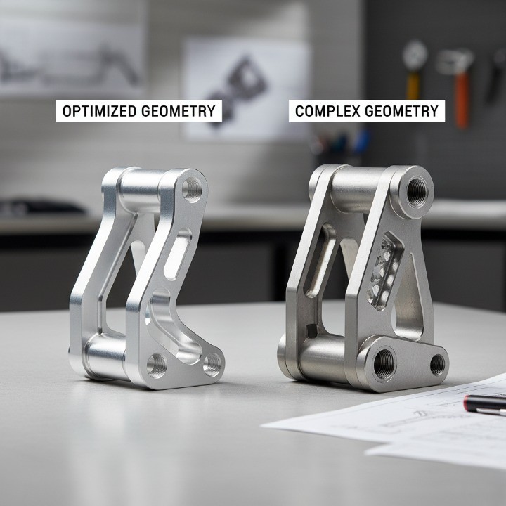
Every design feature in a CNC-milled component carries a cost implication. Complex geometry, tight tolerances, and unnecessary features increase machining time, tooling wear, and material waste, all of which drive up production expenses. For instance, deep pockets require longer tool paths and specialized cutters, while sharp internal corners often demand custom end mills or manual finishing.
In contrast, simplifying geometry and aligning features with standard machining capabilities can reduce costs by as much as 20–40%, according to data from the (External link – Government source). Smart design also improves repeatability and precision—two factors essential for parts used in sectors like automotive, robotics, and aerospace. In short, precision begins at the design stage, not at the machine.
Common design challenges in CNC milled parts
Designing parts for CNC milling presents several recurring challenges that engineers must navigate to achieve the best results:
-
Tool accessibility: Deep cavities, narrow channels, or undercuts may restrict cutter reach or require multiple setups.
-
Thin wall deformation: Excessively thin sections can vibrate or warp during machining, reducing dimensional accuracy.
-
Tight tolerances: While achievable, tight tolerances exponentially increase cycle times and inspection costs.
-
Material selection: Some materials, such as stainless steel or titanium, are difficult to machine and may dictate slower feeds and speeds.
-
Surface finish expectations: Designers often specify aesthetic finishes that add cost without functional benefit.
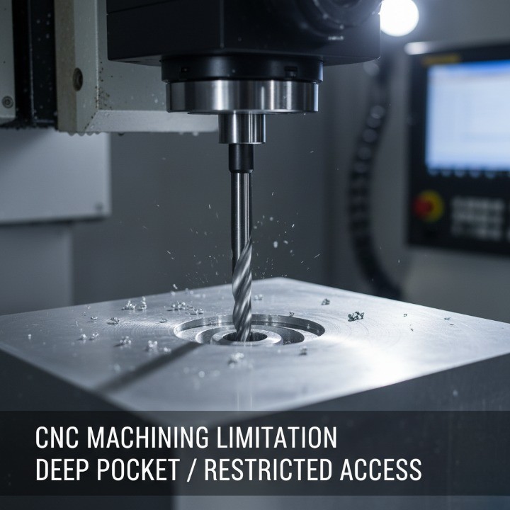
These issues often arise when designs are developed without input from experienced machinists or suppliers. Early DFM consultation can identify and resolve these problems before production begins, saving both time and budget. For example, modifying a deep pocket to a shallower depth or rounding sharp corners can significantly reduce machining effort while maintaining design intent.
Defining design goals — cost, accuracy, and manufacturability balance
Effective CNC design begins with clearly defined objectives. Before modeling a single feature, engineers should evaluate what matters most:
-
Cost efficiency – Optimize material use, minimize setups, and standardize features.
-
Accuracy – Specify tolerances only where functionally necessary; avoid “blanket tight tolerances.”
-
Manufacturability – Ensure geometry aligns with available tooling, machine capabilities, and fixturing.
Balancing these three factors requires collaboration between designers, engineers, and CNC manufacturers. For instance, if a part’s function allows ±0.1 mm rather than ±0.01 mm, cycle time and cost can drop dramatically without sacrificing performance.
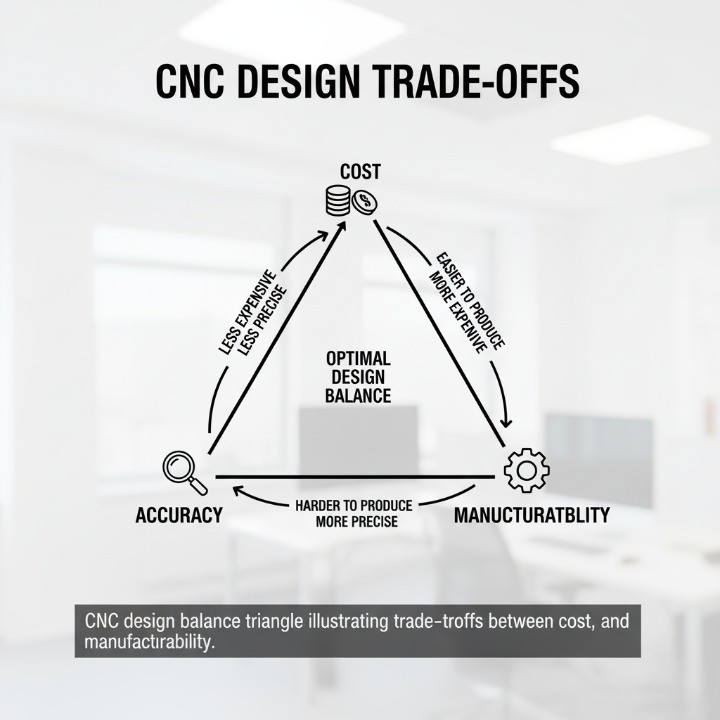
A structured approach—starting with clear design goals, supported by manufacturability feedback—enables designers to make data-driven trade-offs. This alignment between design intent and production capability is what transforms a concept into a high-quality CNC-milled component ready for the real world.
Understanding CNC Milling — Key Concepts Before Designing
Before applying design-for-manufacturability principles, it’s essential to understand how CNC milling operates and the parameters that directly influence your design choices. CNC milling is not just about cutting metal — it’s a precision process that translates digital models into functional components with tight tolerances and repeatable accuracy. By mastering the fundamentals, designers can anticipate manufacturing constraints, reduce revisions, and optimize each part for performance and efficiency.

How CNC milling works?
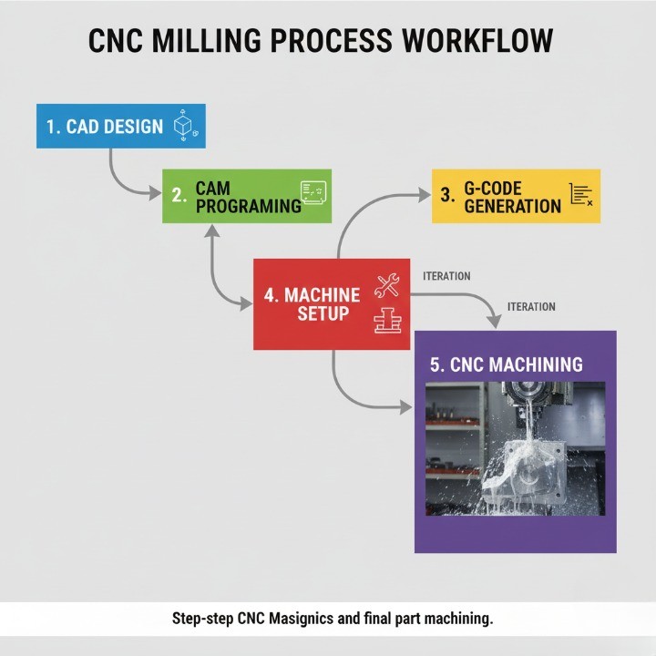
CNC milling uses rotating cutting tools to remove material from a workpiece along multiple axes to achieve the desired geometry. The process begins with a CAD (Computer-Aided Design) model, which is then converted into CAM (Computer-Aided Manufacturing) toolpaths that guide the machine’s movement. The machine interprets these paths through G-code commands, dictating tool motion, feed rates, and spindle speed.
The accuracy of the final part depends on multiple factors:
-
Machine rigidity and alignment
-
Tool sharpness and geometry
-
Cutting parameters (feed rate, depth of cut, speed)
-
Material characteristics and thermal behavior
CNC milling is distinct from turning because the workpiece remains stationary while the cutting tool rotates. This makes it ideal for flat surfaces, slots, holes, and complex 3D contours. Most industrial-grade CNC mills maintain tolerances within ±0.01–0.05 mm depending on the machine class and material.
3-axis vs. 5-axis milling and their design implications
The number of machine axes determines both part complexity and manufacturing efficiency.
| Axis Type | Typical Motion | Suitable For | Design Implications |
|---|---|---|---|
| 3-axis milling | X, Y, and Z linear movement | Flat or stepped parts | Best for simpler geometries and low-cost production. May require reorientation for multiple surfaces. |
| 4-axis milling | Adds rotation around X or Y axis | Parts with holes or features on multiple sides | Reduces setups, improves concentricity. |
| 5-axis milling | Simultaneous movement across 5 axes | Complex organic surfaces, aerospace, and medical parts | Enables machining of intricate geometries in one setup, but requires advanced programming and higher tooling cost. |
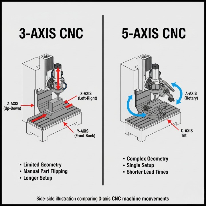
From a design standpoint, 5-axis machining allows for fewer setups, tighter tolerances, and smoother surface finishes, especially on curved surfaces or deep pockets. However, it may not always be the most cost-efficient solution. For parts with accessible geometry, 3-axis machining is often sufficient and more economical.
When selecting between 3-axis and 5-axis production, designers should consider:
-
Geometry complexity: How many faces or angles need access?
-
Volume and budget: Is it a prototype or mass-production part?
-
Tolerance requirements: Are high-precision transitions or freeform surfaces critical?
Key terms every designer should know
To collaborate effectively with machinists and ensure accurate design communication, every engineer should be familiar with these essential CNC terms:
-
Toolpath: The programmed route the cutting tool follows.
-
Feed rate: The speed at which the tool advances into the material.
-
Spindle speed: The rotational speed of the cutting tool (measured in RPM).
-
Tolerance: The permissible dimensional variation in a machined part.
-
Surface finish (Ra): The texture quality of a surface measured in micrometers (µm).
-
Setup: The process of positioning and securing the workpiece for machining.
-
Fixture: A device that holds the part in place to maintain precision.
-
End mill: The most common cutting tool in milling; available in flat, ball, and corner-radius types.
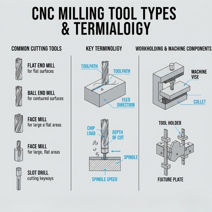
Designers should integrate these terms into their technical drawings and discussions to prevent ambiguity during quoting and production. Misunderstanding terminology often leads to incorrect assumptions about cost, achievable tolerances, or process capability.
Essential CNC Milling Design Guidelines (DFM Best Practices)
Design-for-manufacturability (DFM) is the cornerstone of efficient CNC milling. The objective is simple: design parts that meet performance requirements while minimizing cost, machining time, and risk of error. By aligning CAD models with real machining constraints, you can shorten production cycles, extend tool life, and achieve greater process stability. These design guidelines summarize the best practices that professional machinists and design engineers follow to produce accurate and cost-effective CNC-milled parts.

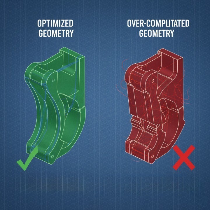
Optimize geometry for machining efficiency
Efficient geometry is at the core of cost-effective CNC milling. Each feature you add to a design directly affects tool paths, material removal rate, and cycle time. Simpler geometries not only reduce machining cost but also improve accuracy and repeatability. Avoid unnecessary undercuts, intricate recesses, or thin ribs that require multiple setups or custom tooling.
Practical optimization guidelines:
-
Use standard radii and fillet sizes that match common end mills (e.g., 3 mm, 6 mm, 10 mm).
-
Keep feature depths below 4–6× the tool diameter to avoid tool deflection.
-
Limit unnecessary step-downs in deep pockets; consider using stepped cavities instead.
-
Minimize sharp transitions—smooth, gradual curves enhance tool stability and chip evacuation.
Plan for tool access and fixturing
Tool accessibility is one of the most underestimated design constraints in CNC milling. If a tool cannot physically reach a surface at the correct orientation, that feature cannot be milled accurately. Poor access can also lead to chatter, vibration, or uneven surface finish.
Best practices for tool access:
-
Maintain open geometries; avoid narrow channels under 3× tool diameter.
-
Design with line-of-sight machining in mind — minimize reorientation.
-
Add chamfers or relief cuts to improve cutter entry.
-
Avoid obstructing features near deep pockets or walls.
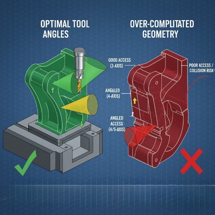
Effective fixturing is equally vital. Every reorientation or additional setup increases both cost and error potential. Consider designing flat reference faces that allow stable clamping. For multi-surface machining, collaborate early with your supplier to determine if 4-axis or 5-axis fixturing is more economical.
Manage internal radii and corner transitions
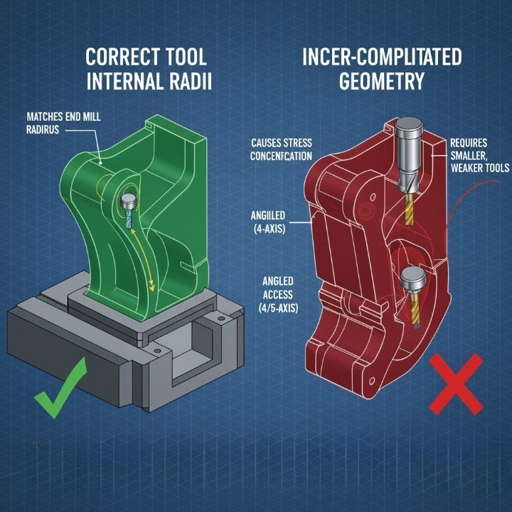
CNC milling tools are round, which means internal corners can never be perfectly sharp. Designing sharp internal features leads to increased tool wear, poor surface finish, and potential tool breakage.
Guidelines for optimal corner design:
-
Match corner fillets to the tool radius or larger (avoid 90° sharp corners).
-
Use 3 mm minimum radius for pockets machined with 6 mm end mills.
-
Apply larger radii wherever possible to enable faster tool paths.
-
When sharp edges are functionally necessary, consider Electrical Discharge Machining (EDM) as a secondary process.
Maintain consistent wall thickness
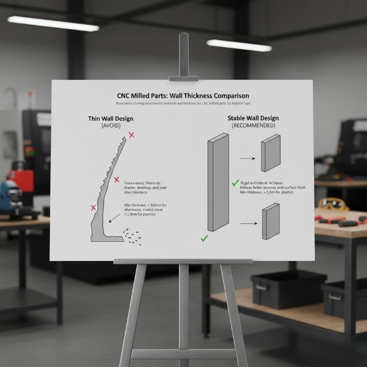
Thin or uneven walls are a common cause of vibration, deformation, and poor dimensional control. During cutting, the tool exerts lateral forces that can deflect unsupported material. Maintaining consistent wall thickness improves stability, reduces chatter, and enhances surface quality.
| Material Type | Recommended Minimum Wall Thickness | Notes |
|---|---|---|
| Aluminum | ≥ 1.0 mm | Excellent machinability; moderate rigidity |
| Steel | ≥ 1.5 mm | Higher cutting resistance; requires more support |
| Plastics | ≥ 2.0 mm | Prone to heat distortion; machine at lower speed |
Design holes, threads, and small features for manufacturability
Holes and threads are among the most frequent machining operations, but they can significantly affect part cost if designed inefficiently. Follow standard diameters and depths whenever possible to avoid tool changes or special taps.
Guidelines:
-
Design holes in multiples of standard drill sizes (e.g., 3 mm, 6 mm, 10 mm).
-
Keep hole depth ≤ 4× diameter for better chip evacuation.
-
Avoid blind holes when through-holes are functionally acceptable.
-
Use standard thread sizes (M6, M8, ¼-20) instead of custom pitch.
-
Maintain minimum wall clearance of 1.5× diameter between holes and edges.
Apply tolerances and surface finishes wisely
Over-specifying tolerances is one of the most common sources of unnecessary cost in CNC milling. Each additional decimal place tightens inspection criteria, prolongs machining time, and requires specialized tools. Apply tight tolerances only where they impact function or fit.
Best practices:
-
Default to ±0.1 mm unless functional requirements dictate otherwise.
-
For critical alignment or bearing fits, use ±0.01–0.02 mm.
-
Clearly differentiate between cosmetic and functional surfaces.
-
Choose surface finishes that match performance needs—avoid excessive polishing for hidden parts.
| Surface Finish | Typical Roughness (Ra µm) | Recommended Application |
|---|---|---|
| As-machined | 3.2–6.3 | Functional prototypes, internal components |
| Bead blasted | 1.6–3.2 | Aesthetic surfaces, even matte texture |
| Anodized (Type II) | 0.8–1.6 | Corrosion resistance, appearance |
| Anodized (Type III) | 0.4–0.8 | High wear resistance, aerospace parts |
These essential DFM principles ensure your CNC designs are not only manufacturable but also optimized for quality, performance, and cost efficiency. Each guideline builds toward creating a balance between design intent and real-world machining practicality—the foundation of successful precision manufacturing.
Advanced Design Considerations
Beyond basic geometry and DFM rules, advanced CNC milling design demands an understanding of material behavior, dimensional stability, and sustainable manufacturing practices. These factors directly influence cost, performance, and long-term reliability. By considering them early in the design process, engineers can create parts that not only perform well but are also efficient to produce and environmentally responsible.

Material selection and its impact on machinability
Choosing the right material is one of the most critical steps in CNC design. Machinability affects everything—cutting speed, tool wear, achievable tolerances, and overall cost. Each material behaves differently under the cutter, influencing feed rate, surface finish, and dimensional accuracy.
General machinability ranking (approximate):
| Material Type | Machinability Rating | Notes |
|---|---|---|
| Aluminum (6061, 7075) | ★★★★★ | Excellent machinability, ideal for prototypes and high-precision components |
| Brass | ★★★★☆ | Smooth cutting and excellent surface finish, but costlier |
| Mild Steel (1018, 1045) | ★★★☆☆ | Balanced performance, moderate tool wear |
| Stainless Steel (304, 316) | ★★☆☆☆ | Work-hardens quickly; requires slower speeds |
| Titanium | ★☆☆☆☆ | Poor machinability, high tool wear and heat generation |
| Engineering Plastics (POM, PEEK) | ★★★★☆ | Light, good for prototypes; may warp due to heat buildup |
Tips for optimizing material choice:
-
Consider both mechanical properties and machining time.
-
For lightweight parts, aluminum alloys are often the most cost-effective option.
-
For corrosion or temperature resistance, stainless steel or titanium may be required but plan for longer cycle times.
-
Always specify material grade (e.g., 6061-T6 vs. 7075-T6) to prevent sourcing confusion.
Thermal and structural stability in milled parts
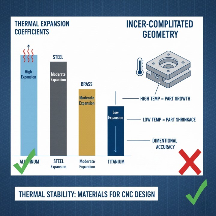
Thermal expansion and structural rigidity are often overlooked during design, but temperature changes and internal stress can significantly affect dimensional accuracy. As cutting tools generate heat, the workpiece may expand slightly, causing deviations in critical dimensions.
Key stability considerations:
-
Thermal Expansion Coefficient: Materials like aluminum expand faster than steel—design with tolerance for thermal movement.
-
Residual Stress: Uneven material removal can release internal stress, leading to warping or distortion.
-
Part Geometry: Long, thin parts deform more easily than compact geometries.
| Material | Coefficient of Thermal Expansion (µm/m·°C) | Notes |
|---|---|---|
| Aluminum | 23.0 | High expansion; use symmetric cuts |
| Steel | 12.0 | Stable, moderate expansion |
| Brass | 19.0 | Slightly higher than steel |
| Titanium | 8.6 | Excellent stability but difficult to machine |
| POM Plastic | 110.0 | Very high expansion, avoid tight tolerances |
Best practices for thermal control:
-
Distribute material removal symmetrically to minimize stress.
-
Use coolant or mist lubrication to maintain consistent cutting temperature.
-
For large parts, allow post-machining stress relief (especially for steel and aluminum).
-
Avoid designing unsupported long sections that may deflect under tool pressure.
Sustainable and waste-efficient design strategies
Modern CNC manufacturing increasingly emphasizes sustainability. Reducing waste, optimizing toolpaths, and choosing recyclable materials not only lower cost but also improve environmental impact. Sustainable design starts at the CAD level—every cubic millimeter of unnecessary material becomes waste in production.
Practical eco-efficient strategies:
-
Material optimization: Use near-net-shape blanks to reduce stock waste.
-
Batch machining: Group similar parts to minimize setup changes and energy use.
-
Recyclable materials: Choose aluminum, brass, or stainless steel, which have high recycling rates (over 90% for aluminum according to World Aluminium Association).
-
Tool life extension: Use coated carbide tools for longer lifespan and less scrap.
-
Digital verification: Simulate toolpaths before production to prevent rework.
Benefits of sustainable CNC design:
-
Up to 20–30% reduction in material waste through optimized layouts.
-
Lower energy consumption and reduced carbon footprint.
-
Enhanced brand value through eco-conscious manufacturing.
By integrating these advanced design considerations—material choice, stability, and sustainability—engineers can achieve superior performance and responsible manufacturing outcomes. These insights not only optimize part quality but also reflect modern industry values of efficiency, innovation, and environmental stewardship.
Cost Optimization in CNC Design
Cost efficiency in CNC milling is achieved not by cutting corners but through strategic design decisions that reduce cycle time, tooling changes, and waste. Every feature on a CAD model directly affects machining duration and cost structure. By optimizing for tool usage, part orientation, and process flow, engineers can often reduce production costs by 25–50% without sacrificing quality.

Use standard tool sizes and cutter paths
Designing for standard tool diameters and cutter paths is one of the simplest yet most effective ways to lower CNC milling costs. Custom tools or nonstandard sizes require special programming, additional setup time, and more expensive cutters.
Best practices:
-
Design features using standard end mill diameters (e.g., 3 mm, 6 mm, 10 mm, 12 mm).
-
Maintain minimum inside radii equal to or larger than tool radius.
-
Avoid deep slots or pockets requiring extended-length tools.
-
Use uniform cutting depths and consistent toolpaths to reduce retooling.
| Tool Diameter (mm) | Typical Application | Recommended Maximum Depth (mm) |
|---|---|---|
| 3 | Fine detail, small pockets | ≤ 9 |
| 6 | General purpose | ≤ 18 |
| 10 | Structural cavities | ≤ 30 |
| 12 | Heavy-duty cuts | ≤ 36 |
Minimize setups and reorientation
Each time a part is removed and repositioned, it introduces alignment error, setup time, and additional operator cost. Reducing the number of setups can significantly improve both efficiency and accuracy.
Design tips for fewer setups:
-
Combine operations into one orientation where possible.
-
Add self-locating features (e.g., datum surfaces or alignment pins).
-
Design parts suitable for 4-axis or 5-axis machining to minimize re-clamping.
-
Consider split designs if features cannot be accessed in a single setup.

Avoid over-engineering and non-functional complexity
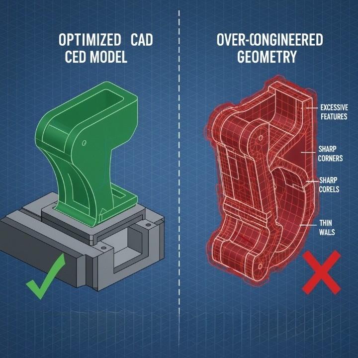
Adding excessive design detail might seem like a quality improvement, but in practice, over-engineering leads to higher cost, longer lead times, and more rework. Every unnecessary contour, fillet, or tolerance consumes resources.
Common examples of over-engineering:
-
Extremely tight tolerances (e.g., ±0.005 mm) where ±0.05 mm would suffice.
-
Decorative grooves or aesthetic cutouts on non-visible surfaces.
-
Custom thread pitches or hole depths without technical necessity.
-
Unnecessary surface finishes on internal or non-critical features.
Simplify without sacrificing function:
-
Prioritize functional geometry first, then aesthetics.
-
Use design hierarchy reviews—ask “Does this feature add measurable value?”
-
Consult manufacturing partners for DFM feedback before finalizing.
Design choices that directly impact machining time
Machining time is the single largest contributor to total production cost. Small design changes can lead to significant time savings when multiplied across hundreds of parts in a production run.
Key design elements influencing machining time:
-
Material removal volume: The more stock removed, the longer the cycle.
-
Cutting path length: Complex contours or unnecessary surface features increase time.
-
Tolerance level: Tight tolerances require slower tool speeds and additional verification.
-
Tool changes: Designs requiring multiple tool diameters or types add setup and calibration time.
-
Part orientation: Poorly oriented parts may require manual repositioning or secondary machining.
Design for efficiency:
-
Use simple, continuous toolpaths whenever possible.
-
Minimize deep pockets and high-aspect-ratio cavities.
-
Maintain a consistent cutting depth to reduce speed changes.
-
Apply roughing and finishing strategies efficiently through CAM software.
Effective CNC cost optimization is not about reducing quality—it’s about smarter engineering decisions that balance performance and productivity. When design, tooling, and process strategies align, the results are higher efficiency, tighter tolerances, and lower overall cost per part.
Common CNC Design Mistakes to Avoid
Even the most experienced engineers can overlook details that complicate CNC machining. These mistakes don’t just increase cost—they also lead to longer lead times, poor tolerances, and potential part rejection. Understanding these pitfalls helps ensure that your designs remain both functional and manufacturable. Avoiding common CNC design errors is one of the fastest ways to improve production yield and lower total cost.
Overly tight tolerances
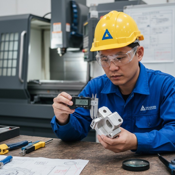
Specifying tolerances tighter than necessary is one of the most frequent and costly design mistakes. Every additional decimal place adds machining time, inspection steps, and potential rework. While precision is essential in critical fits or bearing seats, non-functional surfaces can tolerate looser dimensions.
Best practices for tolerance design:
-
Use ±0.1 mm for general features unless otherwise required.
-
Apply ±0.01–0.02 mm only to precision fits (shafts, holes, mating surfaces).
-
Avoid blanket tolerances across the entire drawing.
-
Always specify geometric dimensioning and tolerancing (GD&T) to clarify intent.
| Feature Type | Recommended Tolerance | Notes |
|---|---|---|
| Non-critical surfaces | ±0.1 mm | Fast, cost-efficient machining |
| Shaft-hole fits | ±0.02 mm | Required for bearing assembly |
| Alignment features | ±0.05 mm | Balance between fit and cost |
| Aesthetic parts | ±0.1 mm | Relaxed tolerance saves cost |
Sharp internal corners and deep pockets
Sharp internal corners are incompatible with the circular geometry of milling tools. When designs include 90° corners or excessively deep pockets, tool wear increases and surface quality deteriorates. Additionally, these features often require secondary processes like EDM, raising both cost and lead time.
Avoid these pitfalls by:
-
Replacing sharp internal corners with fillets at least equal to the tool radius.
-
Limiting pocket depth to 6× tool diameter for most materials.
-
Designing step-down pockets to reduce tool deflection.
-
Using 5-axis machining only when absolutely necessary for undercuts or steep walls.
| Problem Feature | Issue | Recommended Fix |
|---|---|---|
| Sharp corners | Tool cannot cut to 90° | Add corner radius ≥ tool radius |
| Deep pockets | Tool chatter, heat buildup | Use stepped depth or shallow cuts |
| Undercuts | Require custom tooling | Redesign or split geometry |
Unsupported thin walls or tall features
Unsupported structures tend to vibrate or deflect under cutting forces, leading to dimensional errors, chatter marks, or even tool breakage. Designers often underestimate how much rigidity affects accuracy, especially in long, narrow features.
Best practices to avoid instability:
-
Keep wall thickness above 1.0 mm (Aluminum) or 1.5 mm (Steel).
-
Avoid aspect ratios greater than 4:1 (height to thickness).
-
Add ribs or gussets to reinforce tall features.
-
Use balanced toolpaths and moderate feed rates to reduce stress.

Ignoring tool entry and exit paths
Neglecting tool approach and exit clearance is a subtle yet serious design oversight. Without proper entry and exit paths, cutters may leave marks, create burrs, or damage the surface finish. It also increases tool wear and can cause unexpected tool collisions.
Design considerations:
-
Provide entry chamfers or lead-in areas for tools.
-
Avoid abrupt starts and stops in toolpaths.
-
Ensure holes and slots are fully accessible from at least one direction.
-
For high-precision components, design small relief zones at the end of cuts.
| Issue | Consequence | Design Solution |
|---|---|---|
| No entry relief | Surface gouging | Add lead-in or chamfer |
| Abrupt exit | Burr formation | Add exit relief or over-travel zone |
| Confined pocket | Tool vibration | Increase clearance angle |
By understanding and avoiding these frequent design pitfalls—over-tolerancing, sharp corners, unsupported walls, and poor tool access—designers can achieve smoother production runs, lower tooling costs, and superior part quality. Precision begins in design, not correction, and proactive collaboration with your machining partner ensures that every project meets its technical and economic goals.
Surface Finishing Options for CNC Milled Parts
Surface finishing is more than a cosmetic step — it’s a functional extension of the machining process. The right finish improves corrosion resistance, durability, and performance while meeting visual or brand requirements. In CNC milling, finishes also affect friction, assembly fit, and wear resistance. Selecting the optimal finishing process ensures your parts achieve both aesthetic and operational goals.
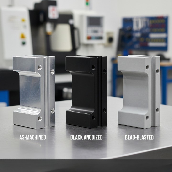
As-machined, bead blasting, anodizing, powder coating, polishing
CNC milled parts can be finished in many ways depending on mechanical function, environmental exposure, and appearance requirements. Each finishing process has unique benefits, limitations, and cost considerations.
| Finish Type | Typical Appearance | Function & Benefits | Common Materials | Notes |
|---|---|---|---|---|
| As-Machined | Smooth with visible tool marks | Fastest turnaround, no post-processing | All metals | Ideal for prototypes and internal parts |
| Bead Blasting | Matte, uniform texture | Removes tool marks, improves aesthetics | Aluminum, stainless steel | Common for consumer and robotics housings |
| Anodizing (Type II) | Satin or colored finish | Corrosion resistance, dye options | Aluminum | Adds ~10–20 µm oxide layer |
| Anodizing (Type III) | Hard, dense coating | High wear resistance, thermal stability | Aluminum alloys | Aerospace and medical-grade parts |
| Powder Coating | Glossy or matte finish | Excellent color range, scratch resistance | Steel, aluminum | Thicker coating (~50–150 µm) |
| Polishing | Mirror or semi-gloss finish | Low friction, visual enhancement | Stainless steel, brass | Labor-intensive, ideal for decorative or medical use |
Choosing the right finish for performance and appearance
Selecting the ideal surface finish requires balancing functional, environmental, and aesthetic priorities. The choice depends on where and how the part operates — in a visible assembly, a high-wear environment, or a corrosive setting.
Functional selection tips:
-
Corrosion resistance: Choose anodizing (Type II or III) or powder coating.
-
Wear protection: Use hard anodizing or polishing for smoother contact surfaces.
-
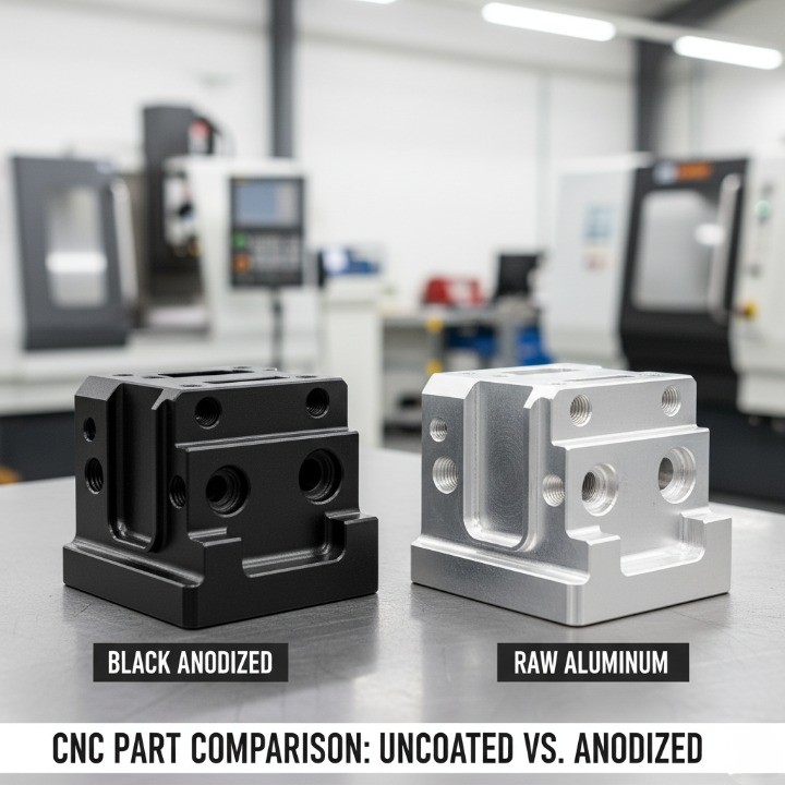
Aesthetic enhancement: Opt for bead blasting before anodizing for a premium matte look.
-
Electrical insulation: Apply powder coating or anodic oxide layers.
Aesthetic and branding factors:
-
Consistent matte textures improve light diffusion for consumer electronics.
-
Polished finishes are preferred for medical instruments or luxury components.
-
Powder coatings allow exact color matching per (External link – Standard reference).
Surface finish standards and measurement (Ra values)
Surface roughness is a measurable indicator of finish quality and directly impacts sealing, friction, and aesthetic feel. Ra (Roughness Average), measured in micrometers (µm), represents the mean deviation of surface peaks and valleys.
| Surface Finish | Typical Ra (µm) | Process Example | Application |
|---|---|---|---|
| As-Machined | 3.2–6.3 | Standard milling | Functional components |
| Fine Machined | 1.6–3.2 | Precision milling | Moving assemblies |
| Bead Blasted | 1.6–2.4 | Bead blasting | Aesthetic covers |
| Polished | 0.4–0.8 | Manual/mechanical | Decorative or medical parts |
| Anodized (Type II) | 0.8–1.6 | Electrochemical | Corrosion protection |
| Hard Anodized (Type III) | 0.4–0.8 | Electrochemical | Aerospace, high-wear parts |
Best practices for specifying Ra values:
-
Define Ra only for critical mating or sealing surfaces.
-
Avoid specifying overly fine finishes unless required — lower Ra values increase polishing time.
-
Match Ra to function; for instance, a sliding surface typically requires Ra ≤ 0.8 µm.
Selecting the appropriate surface finish is both an art and a science. By aligning material choice, part function, and finish type, designers can achieve the perfect balance between appearance, durability, and cost-effectiveness. Each finishing decision impacts the final performance — and thoughtful selection ensures every CNC milled part meets its intended purpose with professional precision.
Preparing and Submitting Your CNC Design
Preparing your CNC design files correctly is essential for accurate machining, faster quotations, and smooth production workflows. A well-structured submission minimizes errors, ensures geometry integrity, and allows your manufacturing partner to deliver parts that meet both technical and cost expectations.

Recommended CAD file formats
Choosing the right CAD file format ensures seamless transfer from design to manufacturing. Incorrect or incompatible formats can distort dimensions, lose tolerances, or misrepresent complex surfaces.
Preferred 3D model formats:
-
STEP (.stp, .step): The gold standard for CNC machining; preserves geometry and tolerance data accurately across platforms.
-
IGES (.igs, .iges): Widely supported but may lose fine surface data during translation.
-
Parasolid (.x_t, .x_b): Highly accurate and lightweight for SolidWorks or Siemens NX users.
-
STL (.stl): Common for 3D printing; not ideal for CNC machining due to faceted surface geometry.
2D drawing formats:
-
PDF: Universal for quoting, dimension reviews, and tolerance verification.
-
DWG/DXF: Essential for laser cutting, engraving, or flat pattern files.
| File Format | Application | Strengths | Limitations |
|---|---|---|---|
| STEP (.stp) | CNC machining standard | Preserves true geometry and tolerances | Large file size for complex models |
| IGES (.igs) | Legacy format | Broad compatibility | May lose NURBS surface fidelity |
| Parasolid (.x_t) | Advanced CAD systems | Compact and precise | Limited support outside NX/SolidWorks |
| Review and quoting | Easy to read and annotate | 2D only | |
| DXF/DWG | Sheet/flat components | Accurate for outlines | Must confirm units and scale |
Including drawings, tolerances, and notes
While 3D models communicate shape, 2D drawings communicate manufacturability. Clear and complete drawings prevent misinterpretations during setup, machining, and inspection.
Your technical drawing should include:
-
Title block: Part name, revision number, material, and scale.
-
Datum references: Define measurement origins for inspection accuracy.
-
Tolerances: Follow ASME Y14.5 or ISO 2768 for consistent interpretation.
-
Surface finish callouts: Specify Ra values or finishing methods (e.g., anodizing, bead blasting).
-
Threads and holes: Define thread type (e.g., M6 × 1.0), depth, and tolerance class.
-
General notes: Include material specification, heat treatment, or coating requirements.
| Drawing Element | Purpose | Example |
|---|---|---|
| Title Block | Identifies revision and ownership | “Part: Drive Housing, Rev C” |
| Datum Reference | Establishes measurement base | “Datum A = Base Plane” |
| Tolerance | Controls dimensional limits | ±0.05 mm for critical fits |
| Surface Finish | Specifies texture | “Ra 1.6 µm bead-blasted” |
| Thread Callout | Defines threaded features | “M8 × 1.25 tapped depth 12 mm” |
Tips for clear communication:
-
Keep all units consistent (prefer millimeters).
-
Add general tolerance notes (e.g., ISO 2768-mK) to reduce clutter.
-
Avoid unnecessary tight tolerances — apply only where functionally required.
-
Provide section or detail views for internal features.
Choosing the Right CNC Manufacturing Partner
Selecting the right CNC manufacturing partner is not just about finding a supplier — it’s about building a long-term engineering collaboration. A qualified CNC manufacturer doesn’t just produce parts; they help optimize your design, streamline production, and ensure consistent quality. The right partner can reduce lead times, improve cost efficiency, and support you from prototype to full-scale manufacturing.

What to evaluate in a CNC supplier?
Choosing a machining supplier requires more than comparing price quotes. The best CNC partners provide technical expertise, process transparency, and reliable quality systems. When evaluating potential partners, focus on these key aspects:
1. Manufacturing capabilities Ensure your supplier supports multiple machining processes — such as 3-axis, 5-axis CNC milling, turning, and die casting — to handle both simple and complex geometries. A multi-capability manufacturer can produce prototypes and large-batch orders without outsourcing.
2. Quality management Verify compliance with international standards like ISO 9001 or IATF 16949 for automotive production. Ask about inspection methods (CMM, optical measurement, surface roughness testing) and request sample quality reports.
3. Material expertise Suppliers with experience across aluminum, zinc, stainless steel, and engineering plastics can recommend the best material for machinability, durability, and cost efficiency.
4. Communication and responsiveness Your CNC supplier should act as an engineering partner, not just a vendor. Evaluate their communication speed, technical support availability, and ability to provide feedback on DFM (Design for Manufacturability).
5. Lead time and logistics Global B2B customers benefit from suppliers with in-house tooling, assembly, and surface finishing, ensuring shorter supply chains and predictable delivery.
| Evaluation Criteria | What to Check | Why It Matters |
|---|---|---|
| Quality Certification | ISO 9001, IATF 16949 | Ensures process control and consistency |
| Equipment Capability | 3-axis, 5-axis, CMM | Matches part complexity |
| Engineering Support | DFM, design review | Reduces errors early |
| Materials Expertise | Metals & plastics | Better machinability and part strength |
| Lead Time | Production flexibility | Faster turnaround and cost control |
Benefits of early supplier involvement (ESI)
Early Supplier Involvement (ESI) refers to engaging your CNC manufacturer during the design and prototyping stages rather than after finalizing the model. This approach helps identify potential manufacturability issues, cost drivers, and material alternatives before production starts.
Key benefits of ESI:
-
Optimized part geometry: Manufacturers can suggest design simplifications that reduce machining time and cost.
-
Better tolerance control: Early feedback prevents unrealistic tolerances that cause unnecessary rework.
-
Material and process matching: Suppliers recommend ideal materials or toolpaths to balance performance and cost.
-
Faster time to market: Collaborative design iterations minimize prototype revisions and lead time.
-
Reduced risk: DFM analysis catches potential issues before machining begins, preventing production delays.
How HM’s one-stop CNC & die casting service supports DFM?
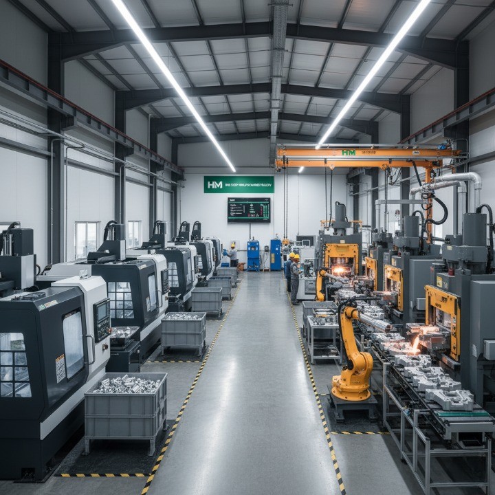
At HM, we specialize in CNC precision machining and die casting — providing a one-stop solution that combines engineering design, manufacturing, surface finishing, and assembly. This integrated approach allows our engineering team to support clients through every stage of product development.
Our DFM support includes:
-
Engineering consultation: Early review of CAD files to assess machining feasibility and tolerance optimization.
-
Material and process guidance: Selecting the best material (e.g., aluminum 6061, zinc Zamak, stainless 304) and process (CNC milling, turning, die casting).
-
In-house surface finishing: Bead blasting, anodizing, powder coating, and polishing for consistent quality.
-
Prototype-to-production scalability: Flexible batch sizes from one-off samples to full production runs.
-
Inspection and quality assurance: CMM measurement, RoHS-compliant finishing, and complete inspection reports.
| Service Capability | Description | Benefit |
|---|---|---|
| CNC Machining | 3-axis, 5-axis, turning, milling | Precision and flexibility |
| Die Casting | Aluminum & zinc casting | High-volume efficiency |
| Surface Finishing | Anodizing, powder coating, polishing | Aesthetic and corrosion protection |
| Assembly & QC | Final assembly and inspection | Complete one-stop solution |
By integrating CNC machining with die casting, HM reduces coordination overhead and ensures design consistency from start to finish. This model eliminates vendor fragmentation and improves delivery reliability — a major advantage for OEMs, brand manufacturers, and engineering procurement teams operating globally.
Frequently Asked Questions About CNC Design
When designing CNC-milled parts, engineers and procurement professionals often have recurring questions about manufacturability, tolerances, and cost optimization. The following section addresses the most common technical questions with practical, data-driven answers based on real-world CNC production standards and best practices.

What is the minimum wall thickness for CNC milled aluminum parts?
The minimum wall thickness depends on material strength, part geometry, and machining forces, but as a general guideline:
| Material | Recommended Minimum Wall Thickness | Notes |
|---|---|---|
| Aluminum (e.g., 6061, 7075) | 1.0 mm | Good balance between stiffness and machinability |
| Steel (e.g., 304, 1018) | 1.5 mm | Higher cutting force; thicker walls needed |
| Brass / Copper | 0.8–1.0 mm | Softer material; easier to machine |
| Plastics (e.g., POM, ABS, Nylon) | 1.5–2.0 mm | Avoid heat-induced deformation |
Design recommendations:
-
For non-structural enclosures, you can reduce aluminum walls to 0.8 mm with careful toolpath planning.
-
For high-load or precision components, keep walls ≥1.5 mm to avoid chatter and deflection.
-
Always consider tool reach and rigidity; longer tools introduce vibration, requiring thicker walls for stability.
What tolerances can CNC milling achieve?
CNC milling can achieve exceptionally tight tolerances, but the achievable accuracy depends on machine configuration, part size, material type, and operator experience.
Typical achievable tolerances (ISO 2768-mK standard):
-
General features: ±0.1 mm
-
High-precision fits: ±0.02–0.05 mm
-
Critical interfaces (e.g., bearing housings): ±0.01–0.02 mm
-
Flatness / perpendicularity: ±0.05 mm per 100 mm length
| Machine Type | Typical Tolerance | Notes |
|---|---|---|
| 3-Axis CNC Mill | ±0.05 mm | Standard for most parts |
| 5-Axis CNC Mill | ±0.01–0.02 mm | Ideal for complex, high-precision geometry |
| CNC Lathe | ±0.01 mm | Excellent for round components |
| Swiss Lathe | ±0.005 mm | Used for miniature parts or medical components |
Pro tips for tolerance specification:
-
Apply tight tolerances only where functionally necessary (fit or motion control areas).
-
Avoid blanket tolerances (e.g., ±0.01 mm everywhere); it increases machining cost dramatically.
-
Include GD&T symbols for clarity on form and positional tolerances.
-
Discuss tolerance feasibility early with your CNC supplier for optimal cost-to-accuracy balance.
How can I reduce CNC machining cost without affecting quality?
Reducing CNC machining costs doesn’t always mean compromising performance. Strategic design and process optimization can cut costs by 20–40% while maintaining—or even improving—part quality.
Key cost-saving strategies:
-
Simplify geometry: Avoid deep pockets, thin ribs, or non-functional curves.
-
Standardize hole sizes: Use standard drill diameters (e.g., 3 mm, 5 mm, 10 mm).
-
Relax non-critical tolerances: Only apply tight tolerances where needed.
-
Use standard materials: Aluminum 6061, 7075, and stainless 304 are widely available and cost-efficient.
-
Minimize setups: Design parts that can be machined in fewer orientations.
-
Combine operations: Consider integrating features that reduce secondary processes (e.g., tapping, polishing).
-
Choose efficient finishes: Use “as-machined” or bead blasting instead of cosmetic-only coatings when possible.
| Design Area | Common Cost Driver | Optimization Tip |
|---|---|---|
| Geometry | Complex contours | Simplify or break into simpler features |
| Tolerance | Unnecessarily tight specs | Apply only where functionally required |
| Material | Hard-to-machine alloys | Switch to machinable alternatives |
| Setup | Multiple orientations | Reorient or consolidate features |
| Surface Finish | Decorative-only specs | Use functional finishes |
Additional insights:
-
Design for standard tool access; custom tooling increases lead time.
-
Batch manufacturing reduces per-unit cost significantly.
-
Use early supplier involvement (ESI) to validate designs before production quoting.
By understanding these frequently asked design principles — from wall thickness to tolerances and cost management — you can create CNC parts that perform better, machine faster, and cost less. Each design choice impacts manufacturability, and early collaboration with your CNC partner ensures precision and profitability in every production run.
Designing Smarter for Better CNC Results
Designing CNC-milled parts isn’t just about achieving geometry—it’s about creating a balance between performance, manufacturability, and cost-efficiency. By applying sound DFM (Design for Manufacturability) principles, engineers and procurement teams can reduce rework, shorten lead times, and deliver higher-quality components with consistent repeatability.
A well-optimized CNC design reflects strategic thinking from concept to production: maintaining realistic tolerances, selecting the right materials, and collaborating early with your manufacturing partner. Every decision—from corner radii to surface finishing—affects machining time, cost, and final product function.
Partnering with a capable and experienced CNC manufacturer ensures your ideas translate into tangible, production-ready results. At HM, we combine CNC machining, die casting, surface finishing, and engineering consultation