
Hard Milling vs. Grinding CNC Strategies for Hardened Steel (50-65 HRC)
Traditionally, once mold steel or parts passed about 45 HRC, most shops pushed finishing to grinding or EDM. That route often forces extra setups, electrode work, and machine changes. Each transfer adds queue time and alignment risk. As a result, you pay more, you wait longer, and you still fight distortion after heat treat.
hard milling and hard turning machine hardened steel up to 65 HRC directly. In this guide, I compare hard milling vs grinding for 50–65 HRC hardened steel and show where EDM still makes sense. I explain when hard milling wins on complex geometry, when grinding still protects CTQs like form and ultra-low Ra, and how a hybrid route—milling instead of grinding
What Is Hard Machining?
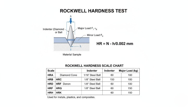
Definition: What “Hard” Means in Machining Terms?
“Hard” refers to hardness measured on the Rockwell scale, commonly Rockwell C (HRC) for steels. In practice, the term “hard machining” describes cutting operations performed on parts that already exceed 45 HRC, where tool wear, heat, and surface integrity become the primary constraints.
Typical Hardness Range: 45–65 HRC and Where 50–65 HRC Fits
Most engineers treat 45–65 HRC as the working definition range for hard machining. The 50–65 HRC band sits in the “finish after heat treat” zone, where you must plan for distortion and where you should treat surface integrity as a CTQ, not an afterthought. You also need a stable process chain because tool wear accelerates fast as hardness rises.
Common Applications: Mold Cavities, Stamping Dies, Shafts, Gears, Wear Components
You see hard machining in parts that need wear resistance and stable geometry after heat treat, such as:
-
Mold cavities and core inserts
-
Stamping and forming dies
-
Shafts and bearing journals
-
Gears and spline features
-
Wear plates, sliders, and guides
-
Valve components and sealing interfaces
These parts often include both complex geometry and CTQ functional faces, which makes process selection a feature-by-feature decision.
Why Hard Machining Exists: Reduce Steps and Finish After Heat Treat?
Hard machining exists because it can reduce the total process chain. Instead of soft machining, heat treat, and then relying on heavy grinding or EDM everywhere, you can finish more geometry directly after heat treat. You often cut lead time by removing electrode loops and reducing machine transfers. You also reduce stack-up error because fewer re-clamps protect your datums.
What Results Are Realistic: Tolerance, Form, and Surface Finish Expectations?
Hard machining can hit strong results, but you must match the method to the CTQ. Hard milling gives you geometry freedom and fast routing, but it responds strongly to setup rigidity and toolpath control. Grinding gives you the most stable path for tight size and form on simple surfaces. EDM solves sharp internal corners and deep narrow features, but it costs time and adds electrode work.
Surface finish targets require clear definitions. Many drawings call out Ra, which standards define as a profile roughness parameter, and industry commonly uses it to control functional behavior and fit. However, Ra alone does not describe directionality or waviness, so you should pair Ra with functional notes for sealing and bearing faces when performance depends on texture. H2 The Big Debate: Hard Milling vs. Grinding vs. EDM
If you want a fast, low-risk decision, use this rule: hard mill for complex 3D geometry, grind for the tightest size/form and lowest Ra, and use EDM for sharp internal corners, deep narrow slots, and features you cannot reach with a cutter. EDM removes material by electrical discharges between electrodes, so it can machine very hard conductive materials without cutting forces, but it adds electrode work and burn time.
Comparison Table: Speed, Cost, Accuracy, Surface Finish, Geometry Freedom, Risk
Most buyers lose money because they compare only “machine hourly rate.” You should compare the full process chain: setups, queues, rework loops, and how each method protects CTQ features after heat treat movement.
| Process | Best fit geometry | What it does best | Typical limits | RFQ notes |
|---|---|---|---|---|
| Hard Milling | 3D surfaces, cavities, blended contours | Fast routing, high flexibility, fewer setups | Sensitive to rigidity, long stickout, chatter | Ask for toolpath type, engagement control, dry/air plan |
| Grinding | Flats, cylinders, simple profiles | Best size/form stability, very low Ra | Less flexible on complex 3D, more setups | Define CTQ faces, form callouts, Ra + directionality |
| EDM | Sharp internal corners, deep slots, fine details | Machines hard materials with no cutting force | Electrode design/build and slow burn time | Ask how many electrodes, burn stages, and cleanup steps |
Surface finish language matters. Ra is the arithmetic mean roughness parameter, but it does not describe directionality or defects by itself.
Hard Milling: Best Fit Applications and Core Advantages
Hard milling wins when geometry drives the job. You can cut 3D cavities, contoured surfaces, ribs, and blended transitions in one routing plan. You also avoid the “EDM loop” on many accessible features, which often cuts lead time because you remove electrode work and machine transfers.
Hard milling also helps you control cost with one lever: fewer setups. Every re-clamp risks datum shift after heat treat. When you keep work in one setup, you protect true position and profile features more easily.
Use hard milling when you can say yes to these points:
-
You can keep tool stickout short and the setup rigid
-
You can run constant-engagement toolpaths on most features
-
Your CTQ surfaces do not demand the lowest possible Ra and form stability
Grinding: Best Fit Applications and Core Advantages
Grinding wins when CTQs demand ultimate stability. It often gives the most repeatable path for tight size and form on flat faces and cylinders. Many grinding processes target very fine surface finishes, and industry references commonly cite high-precision grinding down toward the 0.1 µm Ra class.
Grinding also helps when your inspection plan focuses on form. Buyers often specify flatness, roundness, and cylindricity at low micron levels. Grinding makes those results easier to hold across batches when geometry stays simple.
Choose grinding when these statements match your part:
-
A few functional faces drive the entire print
-
Form matters more than shape freedom
-
You need the safest path for sealing and bearing behavior

EDM: Best Fit Applications and Tradeoffs
EDM wins on features a cutter cannot reach. It can create sharp internal corners, deep narrow slots, and intricate cavities in hardened conductive materials. EDM uses recurring electrical discharges between electrodes in a dielectric, so it avoids mechanical cutting forces.
EDM also brings predictable tradeoffs. Sinker EDM often needs one or more custom electrodes, and electrode work adds cost and lead time. You also plan for cleanup, recast layer control, and downstream finishing where needed.
Use EDM when you face any of these constraints:
-
Sharp internal corners that you cannot radius
-
Deep ribs or slots with extreme aspect ratio
-
Fine detail where tool deflection would destroy accuracy
Hybrid Route: Hard Mill Most, Grind Only CTQ Faces
For many hardened steel parts, the best answer is not “milling vs grinding.” The best answer is “milling plus selective grinding.” You hard mill the majority of geometry for speed and flexibility, then grind only the CTQ faces that demand maximum stability and the lowest roughness.
This hybrid approach works because you assign each surface to the cheapest reliable method:
-
Hard mill everything that does not drive fit, sealing, or bearing behavior
-
Grind only the faces that control function and acceptance
-
Use EDM only where geometry forces it
Quick Selection Rules for Buyers and Engineers
Use these rules before you release the RFQ:
-
If the feature is complex 3D, start with hard milling.
-
If the face controls fit, sealing, or bearing performance, plan grinding.
-
If you need sharp internal corners or deep narrow slots, plan EDM.
-
If only 10–20% of surfaces are CTQ, use a hybrid route.
-
If your drawing only says Ra, add directionality notes for functional faces.
Hard Milling for Hardened Steel: Where It Wins
Hard milling wins when your part has complex geometry and you want fewer setups after heat treat. You get the biggest payoff on 3D cavities, contoured surfaces, and blended features where grinding becomes slow or impractical. Research on hardened steels (about 45–65 HRC) consistently shows hard machining can shorten lead time and reduce processing cost compared with grinding or polishing, when you control stability and surface integrity. If you are sourcing hardened steel machining parts for molds, dies, or wear components, this is exactly where a hard-milling-first route can reduce total cost
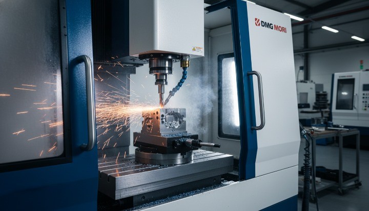
The 60 HRC Shift: Why Many Features Move from EDM and Grinding to Hard Milling?
Modern hard machining sits in the 45–65 HRC range, where coated carbide, ceramics, and CBN-class tools make more features machinable after hardening. You often see the shift around the “finish after heat treat” band because teams want to cut out electrode loops and reduce downstream grinding to only the faces that truly need it.
Hard milling wins fastest when the feature would otherwise force EDM or multiple grinding setups. EDM remains powerful, but it removes material through electrical discharges between electrodes in a dielectric, so electrode planning and burn time can dominate the schedule.
Single-Setup Value: Fewer Hand-offs, Less Queue Time, More Process Stability
Every machine transfer adds queue time and alignment risk. You also lose datum confidence after heat treat movement. Hard milling lets you consolidate work. You often keep rough-to-finish steps on one platform, then reserve grinding for the final CTQ faces. This approach supports the core hard machining value: shorter lead time, fewer steps, and fewer re-clamps.
Use this simple routing mindset: reduce transfers first, then optimize cutting parameters. A “perfect” feed and speed cannot rescue a weak setup chain.
Geometry Value: 3D Surfaces, Cavities, Blends, Local Features
Hard milling excels on geometry grinding cannot reach efficiently:
-
Freeform 3D contours and cavity surfaces
-
Blends, variable radii, and local relief features
-
Ribs, pockets, and sculpted transitions
-
Thin-wall features where a controlled toolpath can reduce rework risk
This geometry advantage explains why hard milling often replaces “grind everything” thinking. Grinding still dominates simple flats and cylinders when form and ultra-low Ra drive the job, but hard milling owns the complex shapes.
Cost Drivers You Can Actually Control: Electrodes, Setups, Rework Loops
Hard milling improves total cost when it removes cost drivers that buyers can actually feel:
-
Electrode design and electrode machining time (EDM) (source:wikipedia.org)
-
Multiple setups across departments and machines
-
Rework loops caused by datum shift and stack-up error
-
Extra polishing steps when the route creates inconsistent surface texture
Research on hardened steel machining highlights practical advantages versus grinding/polishing, including shorter lead times and reduced processing costs, when the process stays stable.
A procurement-friendly way to frame it: do not compare hourly rates—compare process-chain minutes.
Where Hard Milling Is Not the Right Answer?
Hard milling should not be your default when CTQs demand the safest path to size and form:
-
Ultra-tight form on simple geometry (flatness, roundness, cylindricity)
-
Ultra-low surface roughness requirements on sealing and bearing faces
-
Features that force long stickout or weak workholding
-
Sharp internal corners and deep narrow slots that require EDM
Also watch surface integrity. Hardened steels can develop “white layer” or other surface integrity issues under aggressive conditions, and both machining and grinding can influence subsurface state. When surface integrity drives performance, you should plan a hybrid route and demand inspection evidence, not promises. In practice, you also need to align your surface treatment plan—such as polishing, coating prep, or post-process protection—with the functional faces, because finishing steps can change how a hardened surface behaves in service
Hard milling succeeds when you control heat, engagement, and rigidity at the same time. If you only “choose a hard tool” but ignore toolpath and setup stiffness, you will see chipping, chatter, size drift, and surface integrity problems. Research on hardened steels links high cutting temperatures to surface integrity issues such as white layers and microcracks, which can reduce fatigue strength.
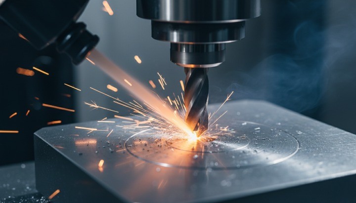
Tooling Selection: What to Use and Why
You should match tooling to the cut type, not just to hardness. Carbide handles most hard milling work when you keep engagement stable. Ceramics and CBN can win, but they demand stricter process discipline.
Use this as a practical starting point:
| Tool type | Best fit in 50–65 HRC | What it gives you | What can go wrong fast |
|---|---|---|---|
| Coated carbide | Most hard milling features | Balanced toughness + heat resistance | Chipping from runout or corner overload |
| Ceramics | High-speed finishing in stable conditions | Very high hot hardness | Thermal shock and brittle fracture |
| CBN | Hard turning and select finishing | Strong wear resistance in hard cutting | Cost and sensitivity to misuse |
Coated Carbide: When It Works Best and Why TiAlN Often Wins?
Coated carbide is the workhorse because it tolerates interrupted cuts better than ceramics. It also keeps risk manageable on mixed-geometry parts.
TiAlN-style coatings often perform well in hard milling because they support high-temperature cutting behavior. Studies describe how TiAlN and the oxide layer that forms during cutting can act as a thermal barrier and reduce heat flow into the tool substrate. That matters because hard milling lives and dies by temperature stability.
Practical buying note:
-
Ask your supplier to specify coating type and tool geometry for CTQ faces.
-
Ask how they control tool wear before it shifts size or finish.
Ceramic Tools: When High Speed Makes Sense and When It Becomes Risky?
Ceramic tools make sense when you can run stable engagement and high surface speed on a rigid setup. They often target productivity in hard materials under dry conditions.
However, ceramics punish inconsistency. They can fail quickly if you shock the edge or overload it in corners. You should treat ceramics as a “process system” choice, not a simple insert choice.
Use ceramics when:
-
You control engagement and avoid sudden load spikes.
-
You keep tool stickout short and workholding stiff.
Avoid ceramics when:
-
You have interrupted cuts, unstable clamping, or long reach tools.
-
You cannot guarantee steady chip evacuation.
Heat Management: Why Dry Cutting Is Often the Default?
Hard milling generates high heat at the cutting zone. You want that heat to leave with the chip, not cycle into the tool and workpiece. Dry cutting often supports stable thermal behavior, especially with modern coatings and constant-engagement toolpaths.
Research on hardened steels highlights that elevated temperature near the surface can drive surface integrity damage. So you should treat heat as a CTQ variable, not a comfort variable.
No Coolant: Thermal Shock Risk and Edge Chipping Mechanism
Coolant can create thermal shock when it hits a hot cutting edge, especially on brittle tool materials. Sources that discuss dry cutting note that thermal and mechanical shock can fracture ceramics, and they often recommend dry cutting for ceramic tools.
Even with carbide, inconsistent coolant delivery can create unstable wear. The edge heats during engagement and cools in air time. That cycle can accelerate micro-chipping. So, you should avoid “random coolant” and choose one consistent strategy.
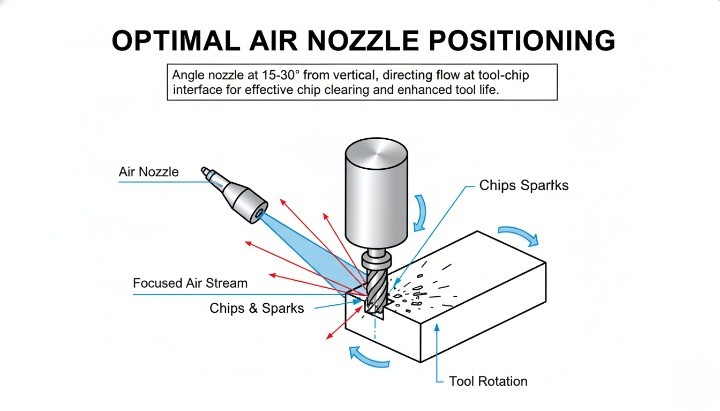
Air Blast: Chip Evacuation and Temperature Stability Checklist
Air blast supports dry cutting because it clears chips and stabilizes heat behavior. Use this checklist:
-
Aim air at the cut to prevent chip recutting.
-
Clear chips from pockets before finishing passes.
-
Avoid dwell in corners and at stepdowns.
-
Keep engagement stable so chips form consistently.
Toolpath Strategy: Trochoidal Milling and Dynamic Milling
Trochoidal milling is a high-efficiency strategy that uses a looping toolpath with low radial engagement and higher axial engagement. It keeps cutting forces lower and more consistent than conventional slotting. That consistency improves tool life and reduces heat spikes.
If you want hard milling to behave like a controlled finishing process, you need this style of engagement control. Otherwise, your tool sees overload at corners and spikes in temperature.
Constant Engagement Rules: Radial Stepdown, Axial Depth, Corner Control
Constant engagement is your main lever for tool life and finish consistency. Use these rules:
-
Keep radial engagement low to reduce peak load.
-
Use higher axial engagement when rigidity supports it.
-
Use smooth arcs into corners to avoid sudden overload.
-
Avoid full-width slotting in hardened steel unless you must.
If CAM settings force “stop and turn” motion, you should expect chipping and chatter. You should fix the toolpath before you blame the tool.
Light Depth of Cut Strategy: High Speed, High Feed, Small Engagement
Many successful hard milling routes use small engagement with stable chip formation. You keep the cut light, but you keep it consistent. You then let speed and toolpath efficiency drive throughput.
This approach works because it protects the edge and controls heat. It also supports predictable offset management during finishing.
Setup and Rigidity: Runout, Stickout, Workholding, and Machine Stability
Hard milling punishes weak setups. You should assume that vibration will show up as tool wear, finish marks, and size drift.
Use this setup checklist:
-
Control runout to protect one-sided edge loading.
-
Minimize stickout to raise stability.
-
Add support in workholding for thin walls and long overhangs.
-
Warm up the spindle before CTQ finishing to reduce thermal drift.
Surface Integrity Control: Avoiding Burn, White Layer, Microcracks
Surface integrity is not only a grinding problem. In hardened steel machining, research links high temperatures to surface damage such as white layers and microcracks, which can reduce fatigue strength. Studies on hard turning also describe white layer behavior and note it can create a brittle surface that supports cracking and failure.
To reduce risk:
-
Keep engagement stable to avoid temperature spikes.
-
Replace tools before flank wear pushes heat into the surface.
-
Avoid dwelling and rubbing passes on hardened faces.
-
Protect CTQ faces with a hybrid plan when risk is high.
Inspection Timing: Thermal Growth, Measurement Repeatability, and CTQ Protection
Inspection must match the physics of hard machining. Parts carry heat after cutting, and that heat can shift size readings. You should measure CTQ features under repeatable conditions.
Use these habits:
-
Let parts stabilize before final measurement.
-
Measure CTQ faces in a consistent sequence.
-
Track tool wear and offsets so size does not drift across the batch.
-
Verify surface finish on functional faces, not on random locations.
Hard Turning: The Lathe Alternative for Hardened Parts
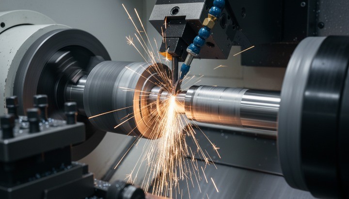
Hard turning finishes hardened steel (often ≥45 HRC) on a CNC lathe, usually with PCBN/CBN tooling. It often replaces grinding on many rotational CTQs when you control rigidity, tool wear, and surface integrity.
When Hard Turning Beats Grinding?
Hard turning wins when the part has rotational CTQs and you want to avoid a separate grinding queue. You often get the biggest payoff on journals, shoulders, and bores where a lathe can hold datums in one setup. For many hardened steel shaft jobs, that single-setup control is exactly what protects bearing fits and seal diameters after heat treat
Hard turning also helps when you need a flexible route. You can turn, gauge, and adjust offsets fast. You can also combine rough, semi-finish, and finish steps without moving the part to another machine.
Use hard turning first when:
-
You have shafts, bushings, bearing seats, or other axisymmetric features.
-
You want fewer transfers after heat treat.
-
You can validate surface integrity and form with a clear inspection plan.
Turned Finish Replacing Ground Finish: What Is Realistic
Hard turning can replace grinding for many functional fits, but it does not replace grinding for every case. You should treat it as a feature-level decision.
Hard turning often works well when you need:
-
Tight diameter control on journals and bores.
-
Controlled chamfers, fillets, and shoulders in one program.
-
A stable route that avoids extra setups and re-clamps.
Grinding still wins when you need the safest path to ultra-low roughness and maximum form repeatability across batches. You should also prefer grinding when the print demands extreme roundness or waviness control that your turning route cannot prove consistently.
Best Fit Parts: Shafts, Bores, Rotational Features
Hard turning fits parts where the functional surfaces are rotational and accessible:
-
Shaft journals, bearing seats, and seal diameters.
-
Bores that control press fits or bearing fits.
-
Shoulders and thrust faces that need consistent geometry.
Hard turning also supports mixed-feature parts. You can hard turn the CTQ diameters, then hard mill the non-rotational geometry. That hybrid approach keeps your grinding scope small and predictable.
Tooling for Hard Turning: Where CBN Fits and Why It Works?
CBN (often as PCBN) exists to machine hardened ferrous materials at high temperature with strong wear resistance. Research notes that CBN/PCBN inserts suit high-speed machining of hardened tool steels because of their high hardness and thermal stability.
CBN also matters for steels because diamond reacts with iron at high temperature, while cubic boron nitride sees broad use for machining steels.
Practical rules that keep CBN stable:
-
Use a rigid setup and avoid interrupted cuts where possible.
-
Control tool wear with planned change points, not “run-to-fail.”
-
Protect corners and shoulders from sudden load spikes with correct approach moves.
Inspection Notes: Roundness, Ra Directionality, and Fit Validation
Inspection must prove function, not just a single roughness number. Many drawings specify Ra, and standards define Ra as an arithmetic mean roughness parameter.
However, Ra alone does not describe spacing, directionality, or profile shape. That matters because turning naturally leaves directional tool marks.
Use an inspection plan that matches the failure mode:
-
Verify size with controlled temperature and consistent fixturing.
-
Verify roundness and cylindricity on bearing fits when performance depends on form.
-
Verify roughness in the correct direction and on the correct functional zones, not random points.
If the part runs under rolling contact fatigue or similar duty, surface integrity matters. Studies link residual stress and white layer behavior from hard turning and grinding to fatigue performance outcomes.
Lead Time Advantage: One Machine Route Versus Grinding Queue Time
Hard turning often reduces lead time because it removes an entire machine step. You can finish hardened rotational features on the turning center, then move only truly grind-required faces to grinding.
This routing also reduces risk. Fewer transfers protect datums. Fewer setups reduce stack-up error. You can then reserve grinding capacity for the small set of CTQs that must be perfect.
Common High-Hardness Materials and What Changes in the Process Plan
Material choice changes tool wear, heat flow, and how you should stage your finishing. Do not pick a route first and “make the material work.” Start with hardness condition, feature risk, and CTQ surfaces. Then choose the mix of hard milling, hard turning, grinding, and EDM that protects your functional faces.
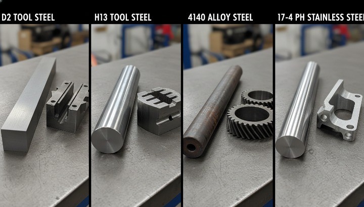
D2 Tool Steel: Extreme Wear Resistance and Tool Wear Control
D2 is a high-carbon, high-chromium cold-work tool steel known for strong wear resistance and high attainable hardness. That wear resistance comes with a cost. The microstructure includes hard chromium-rich carbides, so tools wear fast when you overload corners or recut chips.
Plan D2 like a wear job. Use constant-engagement toolpaths, avoid slotting, and control heat spikes. Keep grinding for the few CTQ faces that demand the lowest Ra or the safest form control.
H13 Hot Work Tool Steel: Stability, Heat Behavior, and Surface Integrity Priorities
H13 is a chromium-molybdenum hot-work tool steel that resists thermal fatigue cracking and keeps strength at elevated temperature. That profile makes it common in hot-work tooling such as die casting and forging applications, where thermal cycling punishes weak steels.
H13 often rewards a hybrid plan. Hard mill most geometry after heat treat, then grind only the sealing, bearing, or datum faces that drive acceptance. You should also watch surface integrity and edge stability on thin features that see heat cycling.
AISI 4140 Pre-Hardened: Production-Friendly Strategy and Cost Control
4140 pre-hardened stock often lands around the Rc 28–36 range, which gives useful strength while keeping machinability workable. Buyers like it for production because it reduces heat-treat distortion risk and shortens the route compared with “machine soft, then harden, then fix.”
Treat 4140 pre-hardened as a stability play. You can hard mill many features and still hold strong CTQs when your setup stays rigid. Use grinding only when the drawing forces extreme form or very low roughness on functional faces.
17-4 PH Stainless Steel H900: Precipitation-Hardened Behavior and Risk Points
17-4 PH is a precipitation-hardening stainless steel (UNS S17400). Many shops machine it in Condition A, then age it to final strength, because aging uses relatively low temperatures and can reduce scaling and distortion compared with high-temperature hardening routes.
In H900, properties shift toward maximum strength, and suppliers commonly publish minimum yield strength values for that condition. Your process plan should reflect higher cutting forces and faster tool wear than in Condition A. You should also define how you will measure Ra and form on sealing or bearing interfaces.
Material Selection Notes That Affect Lead Time and Cost
Use these buying rules when you compare quotes:
-
Ask for the exact condition: annealed, pre-hardened, quenched and tempered, or precipitation-hardened.
-
Match process to feature risk: hard mill complex 3D, grind only CTQ faces, EDM only where geometry forces it.
-
Ask how the supplier prevents rework loops: toolpath type, tool wear rules, and inspection checkpoints.
-
Plan finishing after heat treat movement: re-establish datums before you chase microns.
Design Tips for Hard Machining: DFM Rules Engineers Can Use
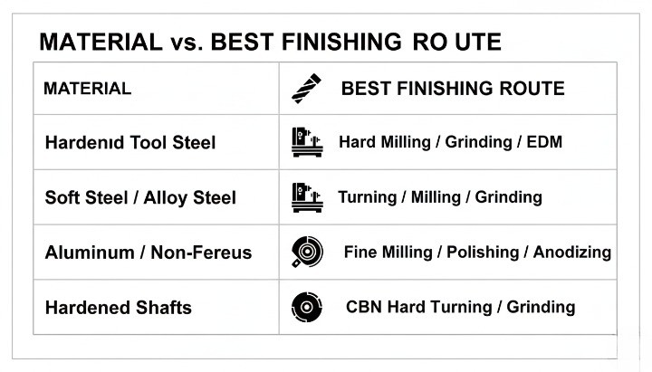
Design for hard machining by controlling three drivers: corner accessibility, rigidity, and CTQ zoning. If you shape features around stable tool engagement and stable datums, you reduce EDM dependency, protect surface integrity, and cut rework after heat treat distortion. Heat treatment can distort parts and change size, so your design should assume movement and plan re-location features accordingly.
Avoid Sharp Internal Corners: When EDM Becomes Mandatory
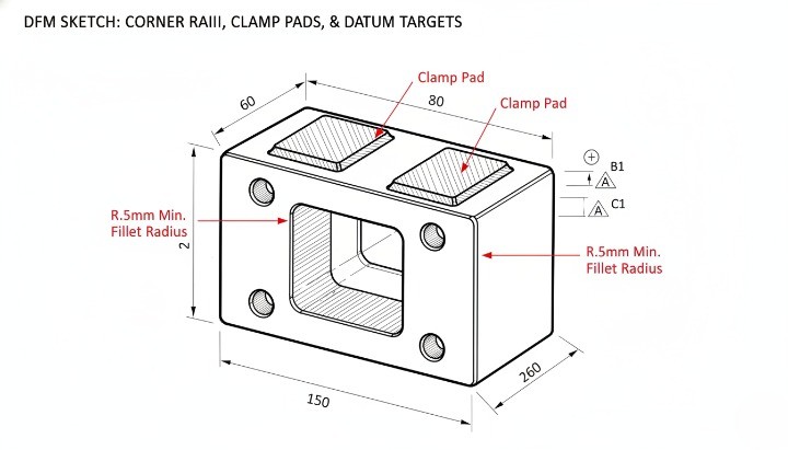
Sharp internal corners force slow and expensive processes. Milling tools have a radius, so they cannot generate a true sharp inside corner. When your design demands a near-zero internal radius, you often push the job to EDM.
Wire EDM is commonly used for tight-radius inside corners and narrow slots in hard conductive materials. To keep the route fast, specify a practical internal corner radius wherever function allows.
Use these rules:
-
Add internal radii to pockets and cavities whenever possible.
-
Avoid “needle slots” and deep narrow features unless they are truly functional.
-
If you must use EDM, limit EDM surfaces to the minimum required zones.
Rigidity Is King: Design Clamp Zones and Support Surfaces
Hard machining punishes vibration. You can reduce risk at the design stage by giving the supplier better clamping options and better support geometry. A rigid clamp plan often matters more than the difference between two cutting tools.
Do this on purpose:
-
Add clamp pads on non-functional faces.
-
Add support flats near thin walls and tall ribs.
-
Avoid long unsupported spans that amplify chatter.
-
Keep critical faces away from obvious clamp marks and deformation risk.
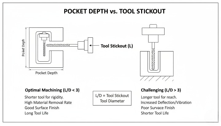
Reduce Long-Reach Tools: Depth-to-Diameter Rules for Pockets and Walls
Long-reach tools reduce stiffness, raise vibration, and increase tool wear. In hardened steel, long stickout also raises surface integrity risk because the tool rubs and heats the surface when chatter starts.
Design features to shorten reach:
-
Use open pockets instead of deep closed pockets when possible.
-
Break deep pockets into stepped depths.
-
Add relief access so the tool can approach without extreme overhang.
-
Avoid deep, narrow ribs with no clearance for chip evacuation.
Tolerance Expectations: What Hard Milling Can Hold Versus What Requires Grinding
Hard milling can hold tight results on stable features, but grinding still gives the safest path for the tightest size and form on simple geometry. Your design should separate “must be perfect” CTQs from “functional but tolerant” geometry. If you want a quick reference for how tolerance choices affect routing and cost, see our guide on CNC machining tolerance.
Use this CTQ logic:
-
Put the tightest size and form requirements on the few faces that truly drive function.
-
Use GD&T symbols consistently so inspection matches intent. ISO 1101 defines the symbol language and rules for geometrical specification.
-
If you need maximum roundness or flatness stability, plan grinding on those faces.
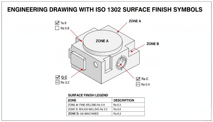
Surface Finish Zones: Where Tool Marks Are Acceptable and Where They Are Not?
Surface finish problems often start as a drawing problem. If your print uses one roughness callout everywhere, suppliers will over-process low-risk faces or under-process functional faces.
Control this with zoning:
-
Define sealing faces, bearing faces, sliding faces, and cosmetic faces as separate zones.
-
Specify surface texture clearly using standard drawing practice. ISO 1302 specifies how to indicate surface texture on technical documentation.
-
Add directionality notes on functional faces when texture direction matters. Ra alone does not explain direction.
Heat Treat and Datum Strategy: Design Features That Help Re-Location After HT
Heat treat distortion is normal. Your design should assume size and shape change and make re-location repeatable. Sources note that every part will distort to some degree in heat treat, and that planning for it reduces surprises.
Build re-location into the design:
-
Add datum targets or datum pads that survive heat treat and finishing.
-
Avoid relying on thin, flexible surfaces as primary datums.
-
Keep a consistent datum scheme from machining to inspection to assembly.
-
Leave controlled finishing stock on grind-required CTQ faces, not everywhere.
Quality and Procurement Checklist for Hardened Parts
You qualify hardened-part suppliers by evidence, not promises. If your RFQ leaves gaps, suppliers guess. Their routes diverge, their quotes swing, and your program absorbs the risk.
Use this checklist to lock the process chain early. You will reduce lead time surprises, prevent inspection disputes, and keep grinding limited to true CTQ faces.

RFQ Inputs That Prevent Quote Swings
You prevent quote swings when you remove ambiguity. Hardened steel jobs fail most often on missing hardness condition, missing CTQ zoning, and missing inspection evidence.
Use this RFQ input table as your baseline:
| RFQ input | What to specify | Why it matters for cost and risk |
|---|---|---|
| Material + condition | Grade, condition, and hardness target/range | Condition drives tool wear, distortion, and routing decisions |
| Heat treat | Standard, process owner, and required certification | Heat treat movement changes datums and final size |
| CTQ list | Size, form, and surface finish per functional face | Suppliers must plan grinding scope and inspection method |
| GD&T | Datums, callouts, and interpretation rules | GD&T defines how you measure and accept geometry (ISO 1101) |
| Surface texture | Ra targets and where they apply | Surface texture indication rules come from ISO 1302 |
| Edge requirements | Edge break, burr limits, and undefined edge rules | Undefined edge indication uses ISO 13715 |
| Quantity + schedule | Prototype qty, annual demand, and ramp | Tool life strategy and sampling plan depend on volume |
| Finish and protection | Rust prevention, packaging, and handling rules | Finished hardened faces scratch easily and fail silently |
If you only write “grind where necessary,” suppliers will disagree on what “necessary” means. Put grinding on named CTQ faces. You will cut rework loops and prevent scope creep.
What to Ask for in the Process Plan: Tooling, Toolpath, Heat Management, Setups?
A good supplier can describe the route in plain English. You should request a short process plan that includes the decisions that control stability.
Ask for these items:
-
Planned route: hard milling, hard turning, grinding, EDM, and where each applies
-
Setup count and datum plan after heat treat
-
Tooling type and coating for CTQ faces
-
Toolpath type for hard milling (constant engagement strategy)
-
Heat management approach (dry strategy and chip evacuation method)
-
Stock-to-leave plan for grind-required faces
-
Tool wear control rule and offset update method
Require the supplier to name the control points. A supplier who cannot explain setup strategy usually cannot repeat results.
Proof Package to Request: FAI, CMM Report, Surface Finish Report, Photos of CTQ Faces
Your proof package should match the failure modes of hardened parts. Size alone does not protect function. Form, surface texture, and edge condition often drive performance.
Request this proof package for first articles:
-
FAI report with ballooned drawing and results per feature
-
CMM report for GD&T features tied to datums (ISO 1101 context) Surface roughness report with measurement locations and direction notes (ISO 1302 drawing indication)
-
Photos of CTQ faces and edge zones under consistent lighting
-
Heat treat certification when you buy hardened condition externally
Trial Run and Capability Evidence: What to Request Before Mass Production?
A prototype proves feasibility. A trial run proves repeatability. You should request a short trial run when the program has real production risk or high CTQ sensitivity.
Use this trial run checklist:
-
Confirm the route runs at planned production feeds and speeds
-
Confirm tool life behavior and define a tool change rule
-
Confirm size and form stability across multiple parts in the run
-
Confirm measurement repeatability using the same fixtures and conditions
-
Confirm packaging protects functional faces during shipping and handling
If your program follows automotive-style requirements, PPAP provides a structured approach to prove the production process meets design record and specification requirements during an actual production run. You can apply the same logic even outside automotive.
Acceptance Criteria: Tool Marks, Edge Break Rules, Rework Limits
Acceptance criteria prevent last-minute disputes. You should define what you accept on non-critical faces, and what you reject on functional faces.
Define these items in writing:
-
Tool mark policy by zone: functional, sealing, bearing, cosmetic
-
Edge break rules and burr limits using a consistent edge indication approach (ISO 13715 helps for undefined edges)
-
Rework limits: how many rework cycles, and what inspection repeats
-
Surface texture rules: Ra target, measurement length, and measurement direction (ISO 1302 indication framework)
If you do not define rework limits, rework becomes a hidden cost center. You will see delays and inconsistent surfaces.
Hybrid Planning as a Cost Lever: Grind Only What Must Be Perfect
The cheapest stable route often uses a hybrid plan. You hard mill or hard turn most geometry after heat treat. You grind only the CTQ faces that require the best size/form stability and the lowest roughness.
Use this decision rule:
-
Hard mill for 3D geometry and access.
-
Hard turn for rotational CTQs when it replaces grinding safely.
-
Grind only named CTQ faces.
-
Use EDM only where geometry forces it.
This approach reduces setups, reduces queue time, and protects datums. It also gives you a clean procurement story because every face has an assigned method and a defined inspection proof.
Troubleshooting: The Fast Fix Guide
Fix the process chain in this order: setup stability → engagement stability → heat stability → measurement stability. Most “mystery” defects come from one of these four. Milling chatter research repeatedly links instability to tool/work system dynamics and factors like runout and damping, so you should treat vibration as a system problem, not a tool-brand problem.
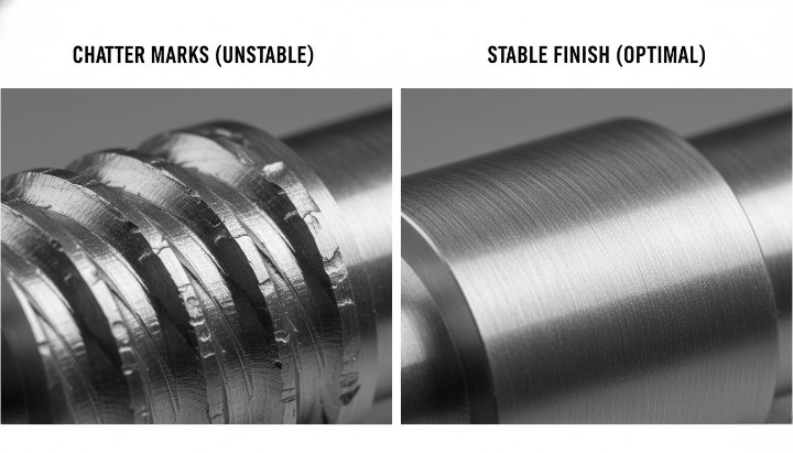
Hard Milling Issues: Chatter, Tool Chipping, Rapid Wear
Chatter usually starts when your system loses stiffness or when engagement spikes in corners. Tool chipping often follows the same root cause. Milling chatter literature highlights the role of dynamic stability and runout in chatter behavior.
Use this fast diagnosis table:
| Symptom | Most common root cause | Fast fix you can apply today |
|---|---|---|
| Chatter marks on walls | Tool overhang too long, weak workholding | Shorten stickout, add support, reduce axial reach |
| Chatter in corners | Engagement spikes, sharp direction changes | Use constant-engagement paths, smooth corner arcs |
| Edge chipping early | Runout, interrupted engagement, corner overload | Reduce runout, avoid slotting, lower engagement |
| Rapid wear, heat tint | Rubbing from worn tool or unstable chip evacuation | Change tool earlier, improve chip evacuation, avoid dwell |
Try these practical moves first:
-
Reduce stickout and increase rigidity before you change feeds and speeds.
-
Reduce radial engagement and avoid full-width slotting in hardened steel.
-
Use constant engagement motion in corners to avoid sudden force peaks.
-
Set a tool change rule before wear causes rubbing and heat spikes.
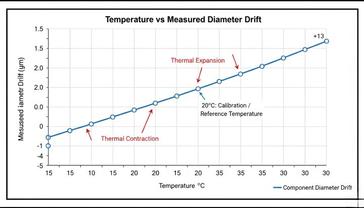
Hard Milling Issues: Size Drift and Thermal Effects
Size drift often has a thermal root cause. Machine structures expand with temperature, and positioning can drift during warm-up and load changes. A Heidenhain technical note describes thermal drift sources in machine tools and notes that changes in length can be significant over short periods without proper control.
Use this checklist when size “walks” during a run:
-
Warm up the spindle and axes before CTQ finishing.
-
Keep finishing passes consistent in time, load, and toolpath pattern.
-
Measure parts at repeatable temperature and timing, not “right after cutting.”
-
Separate roughing heat from finishing accuracy with a short cool-down.
-
Validate offsets using a stable master feature, not a random dimension.
 Grinding Issues: Burn, Waviness, Taper
Grinding problems often look like “finish issues,” but they start as heat and wheel condition issues. Excessive heat can cause grinding burn and thermal damage, and industry and research sources note it can reduce component performance and fatigue life.
Burn (thermal damage)
-
Typical causes: too much energy into the surface, dull wheel, poor dressing, wrong parameters.
-
What to change first: dressing strategy, wheel spec, infeed, and coolant delivery consistency.
-
How to detect: microhardness and residual stress methods appear in NDT discussions of thermal damage in hardened steels.
-
Typical causes: wheel runout/eccentricity, unfavorable wheel-to-work speed ratios, unstable setup.
-
What to change first: correct wheel true/dress, adjust speed ratio, and use stable spark-out practice.Taper
-
Typical causes: improper dressing alignment, inconsistent support, wheel wear, machine condition.
-
What to change first: verify dressing condition matches grinding position, stabilize supports, and correct wheel wear behavior.
Use this quick “stop the bleeding” order:
-
Dress and true the wheel correctly.
-
Reduce heat generation to prevent burn.
-
Stabilize speed ratio and spark-out for waviness.
-
Re-check supports and alignment for taper.
EDM Issues: Overburn, Corner Accuracy, Electrode Wear
EDM removes material by recurring electrical discharges between electrodes in a dielectric liquid. That means EDM problems often trace back to electrode condition, wear, and flushing control.
Common issues and fast fixes:
-
Overburn (oversize cavity): reduce aggressive settings, improve flushing stability, and confirm electrode compensation.
-
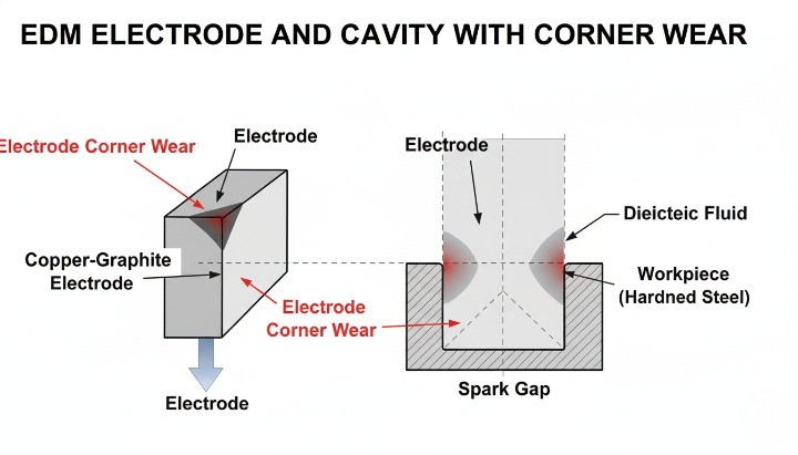
Corner accuracy loss: EDM corner regions see higher wear, and EDM glossaries describe corner wear as a known phenomenon.
-
Electrode wear drift: electrode end wear is real and must be planned with wear allowances and strategy.
Use this procurement-level control rule:
-
Ask the supplier to state electrode count, expected wear behavior, and how they compensate corners. If they cannot answer clearly, expect schedule and accuracy surprises.
Conclusion
Use hard milling for complex geometry, hard turning for rotational CTQs, and grinding for ultimate form and finish on the few faces that must be perfect. This rule cuts machine transfers, protects datums, and reduces the rework loops that drive total cost on 50–65 HRC hardened steel.
If you want a routing recommendation you can trust, send your drawing, CTQ list, hardness condition, and surface finish targets. I will map each CTQ face to the lowest-risk process and define what evidence you should request before you approve production.